Saturday, June 06, 2015

FT-707 repair (8) No output on 12, 17 and 30m band

This one was not obvious for me, still isn't completely understood, only fixed, one of the reasons for not "getting there" faster was I was also having low to none output on 20m, so was suspecting something on the bandpass filters or the associated switching circuit. The filter weren't making much sense because reception was good...it had to be something else.
As soon as I figure out that low output on 20m was due to improper bandpass tune it become obvious which way to go for finding the actual issue.

This is the board in question and the problem is around there...(RF unit PB2093b) !:


Somewhere...:


So what I did was disconnecting the output to the PA and place the scope to check for the level before amplification, after "tuning" the 20m band filter only no power on 12 , 17 and 30m band... so what is common between the bands and only on the TX circuit if I excluded the filters?:


So it was starting to be obvious that the issue was with the associate circuit of Q04, started measuring on the anode of D20 and noticed the bias was smaller every time I selected 12, 17 or 30m band and keyed the transmitter, the bias is also dependent on TX 13.8 (pin 3) from J02 plug, so for each test transmitting must be done. The only cause of smaller bias can only be diodes  D21, D71 and D72, impossible for 3 diodes to be out of spec/broken at the same time and since the voltage droped they were for sure working (an open diode would keep the bias high and a short one very low, was not the case in either). So I lifted the diodes and voila', everything back to life. I'm sure the actual "fault" is somewere else, measured R06 and is spot on so could be any of the other parts. As soon as I have patience and more time will try to dig furter.
I think Yaesu might have placed the 3 diodes in the circuit after checking that probably some bands had excessive power and that as a way to limit a little on the output since the diodes will drop the bias lower and the series of D20 with the PN junction from base to emitter, at the moment I see no other reason for the use of the diodes there and only on these 3 bands, it should not be curing any instability since the band's are not even sequential....

Here the "offending" diodes lifted?


And already outputing some power into a dummy load with the watt-meter in the 15W scale and the carrier control fully counter-clockwise (low output).


..I will leave as it is for now, at least this unit I can consider as fully operational....

On to the next unit, the blue light one!

Have a nice weekend!


Sunday, May 31, 2015

FT-707 repair (7) External mic

Ok, this time the FT-707 is not the usual suspect.

I started testing transmission since reception looks stable now (more on it on latter posts).
First test showed the the mic ptt was not working, it was "wired to the FT-707" according to the vendor.... let's have a look:


Wrong, it was not wired to the FT-707, all of the wires were badly soldered, with some loose strands and one of the nedeed pins (7) had not even a small mark showing signs of any soldering... oh well...


After rebuilding and some cleaning I notice that it was a litle hard releasing the PTT switch. Let's open the mic to see if it is the release spring worn out or some other issue. After testing I notice the black plastic from the PTT was rubbing a litle against the outer case so I filled inside a little bit..


 ..and now, much better, honestly the MIC in fact has a good internal/electronic design but the mechanical part that's another story. That's poor quality control or the plastics expanded over time which is also likely.


 And after some small cosmetic cleaning here it his:


On to testing the radio again... less than 5w out... this is the first time I tough: it goes for parts... well it was ALC preventing more power, I didn't gave up, and after some tunning it's now "limited" to around 50 during this testing phase, I got easily the, promised by Yaesu, 100w during tests.
Still have to test again in SSB with the mic since I was using CW/AM and only the MIC PTT or MOX.
The other set (the blue color one) it's the same from what I've seen, also I suspect a cap or a transistor will explode shortly since there's some background noise on key down... will see!

Have a nice week!

Saturday, May 30, 2015

FT-707 repair (6) Display "dot"

On last post I noticed the decimal dot not working in one of the FT-707 units.


I was hoping for a simple cable broken and not the 7 seg display... it was the cable!

Now it's fixed:


Here's the reason, cable broken on the endpoint, the "missing" one is colored grey coming from the counter unit. The X in the picture marks the spot for the missing "dot" cable:

Had to loosen the from panel a litlle to manage to solder the cable there since the space is short.

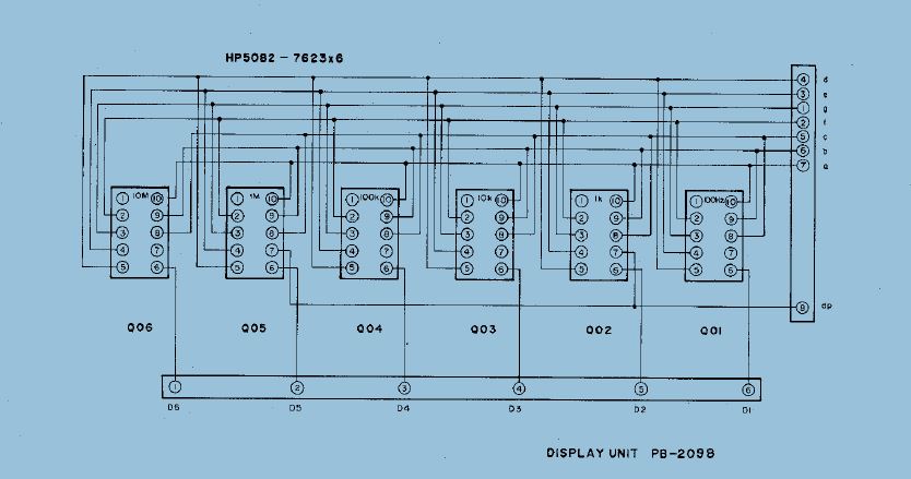
 Here's for future reference, if deeper troubleshooting needed, the interconnection between the display counter unit and the 7 segments LED display in the front panel:


 The output of the counter unit to the LED display
 The LED unit in the from panel, wires are soldered directly from the PCB to the two plugs on the counter unit:


The pint out for the 7 seg LED display used in this radios, I think are similar to FT-107 and others.


Have a nice weekend!

Tuesday, May 26, 2015

FT-707 repair (5) LED lamp replacement

Another fix on one of the FT-707 duo. This unit didn't have the VFO dial ligh's working.

I could had bought those small grain of wheat original bulbs for replacement, instead decided to try LED light on the display, thinking in long term without further maintenance. Got two 3mm high brightness white LED's and placed a 680 Ohm resistor in series across both to limit the brilliance, before placement tested with 330 Ohm limiting resistor and tough it was to much bright.

Here's the outcome (original unit on top, LED fitted unit bellow):


I guess the blue color is because the LED's are white and the rubber grommets blue, maybe with Yellow would stay close to original, anyhow I like it.


And night time, again LED unit bellow:


Now the fixing job, bellow picture, the board with the bulb and LED connections, I removed the frequency counter module (above the VFO box) to better access this board:


The rubber receptacles for the lamps with original bulbs still in place:


Removing them it's just a matter of gently pulling the blue cable. Inserting the LED's it's also easy.

It was a fast job, just need to pay a little attention to not break any of the cables that connect on the board. Fitting the square LED's on the openings of the from panel was also easy.

Done!

Don't know if you noticed and I just noticed yesterday, one of the units doesn't have the decimal points on the frequency display, I hope it's just a wire...or soon I will have a degree on FT-707 fixing!

Have a nice day!

Monday, May 25, 2015

FT-707 repair (4) 10m B crystal

Here's a fix for those who own a FT-707 converted to CB and need to revert back but don't have the original crystals (should work also on the FT-902 and others sharing similar design).

I just request the price, from an Yaesu distributor, for the original 10m band crystals (A,B,C and D). Price quoted was 18 Eur each. Well that's not in my budged since I will need 8 crystals (4 on each set) and that would give the wonderfull sum of  144 Eur, I almost can buy a radio for that money! Guess will have to wait for someone to sell a complete board from a scavenged unit, I've seen premix oscillator boards selling, on online auction sites, for half the price and with all the crystals there.

Anyhow I'm not to be stooped by this, after some calculation I beted that an crystal around 14Mhz will do the overtone job....bought a 14.318 Mhz unit by a woping 0.28 Eur (that's 28 cents) and replaced the crystal, on the 10m D band place, just for testing since I don't have the oscillator coil on 10mB, and this was the result:


I works, spans reception from 28.436 to 29.004 Mhz with the oscillator at 42.972Mhz (14.324Mhz) ! Perfect! Adjusting the premix oscillator variable coil was needed since it was set to the previous CB frequency.

So, for the 10m B position, i'm sorted, now I need to find the other 10m band crystals,  I was looking before on old crystalized scanners crystals and also model control ones, so far no luck on the exact frequencies. There are some specialized sites selling the needed crystal's at around 10 Eur each, still think it's too much for a piece of rock...

If by any chance you know where to find the following crystal's (cheaply) just let me know, apreciate:

The red cross one is the 14.318Mhz one tested. These 14.318Mhz crystals are also found on computer motherboards if cheaper, than 0.28Eur, source is needed!


Have a nice week!


Monday, May 11, 2015

FT-707 repair (3) No LSB reception

Ok, LSB issue sorted.


This one was easy, decided to check first the mode switch at the entrace point and then going from there, I was thinking it could be aging of the LSB crystal since on a previous test while troubleshooting the other issues on the radio fiddling with the LSB trimmer cap hadn't notice any audio change.


 There was no need to look further, the problem was obvious, a broken connection providing the 8v for the LSB BFO oscilator (in fact to the crystal switching diode in the BFO oscillator) and that explains why changing the trimmer position had no effect on audio, it was not even oscillating:


Relevant schematic part:


Now on to set number 1, the external ACC and the dial bulb to fix....

Have a nice week!

Sunday, May 10, 2015

FT-707 repair (2) 20 and 30m not working

Ok, FT-707 set number 2 has now 20 and 30m band working!


In fact it has 80 to 12m plus 2 cb 500Khz segments working now, missing two coils and two crystals to restore the 28 to 29Mhz range (10mA and 10mB).

This was a tricky problem, since I had 30m and not 20m correctly and the 20m premix was having low power so I suspecting mostly from the switching of the 20m premix filter and someting on the LPF for the 30/20m band because if I disconnect the LPF switching cable it would work on 30.

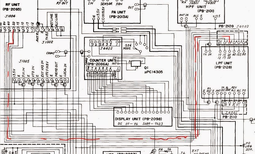
After following the switching line schematics for the LPF filtering:
 

..and local oscillator:

And bandpass filtering:


Eventually... I figure it out in the middle of this mess:


Previous screwdriver expert had incorrectly connected the band switching cabling for 30m, marked as red in the picture, it was incorrectly connected to the LO switching side of the rotating switch. Luckily was not injecting 8v directly to ground when you switched the 30m band..


 ....since the +8v was missing on the band selector also.
 
 By the way, the text notation for "a" and "b" switch's assembly are reversed from the main schematic, tough the schematic is correct in terms of connections.

I would not have been impossible to figure the problem without the manuals, thank you Yaesu!

Now I have to figure it out what's wrong with LSB, I have some distortion and low audio, since the chain is basically the same as USB I suspect one of the two oscillators in line, the LSB and the "whith" one.

More fun in the future...

Have a nice week!