Sunday, May 27, 2018

Teensy 3.6 + 2.8" TFT LCD Display SPI Serial 240*320 ILI9341 connection and code

Just doing some experiments with a Teensy 3.6 microcontroller board, a graphical display and some other bits and pieces.
Since it was not easy to find a single source of information with a code example and pin connections, here's a compilation of it:

Schematic:


For testing porpoises the supply is not needed as long as USB power cable is connected to the board.

Bellow the code to run:

/////////////////////////////////
/*
  Just place some text on the ILI9341 display using a Teensy 3.6
  CT2GQV 2018
*/

#include <Wire.h>
#include <SPI.h>
#include "font_Arial.h"
#include <ILI9341_t3.h>


#define BACKLIGHT_PIN   3
#define TFT_DC          20
#define TFT_CS          21
#define TFT_RST         255  // 255 = unused. connect to 3.3V
#define TFT_MOSI        7
#define TFT_SCLK        14
#define TFT_MISO        12

ILI9341_t3 tft = ILI9341_t3(TFT_CS, TFT_DC, TFT_RST, TFT_MOSI, TFT_SCLK, TFT_MISO);


// Pin 13 has an LED connected on most Arduino boards.
// Pin 11 has the LED on Teensy 2.0
// Pin 6  has the LED on Teensy++ 2.0
// Pin 13 has the LED on Teensy 3.0 and 3.6 by the way
int led = 13;

void setup() {               
  // for the built in LED.
  pinMode(led, OUTPUT);    
  // for the backlight
  pinMode(BACKLIGHT_PIN, OUTPUT );
  analogWrite(BACKLIGHT_PIN, 128); // 0 to 255

  tft.begin();
  tft.setRotation( 3 );
  tft.fillScreen(ILI9341_BLACK);
  tft.setCursor(10, 1);
  tft.setTextSize(2);
  tft.setTextColor(ILI9341_ORANGE);
  tft.setFont(Arial_14);
  tft.print("This side UP");
   tft.setCursor(50, 20);
  tft.setTextSize(2);
  tft.setFont(Arial_10);
  tft.print("Arial 10 font");
 
}

// the loop routine runs over and over again forever:
void loop() {
  // it just blinks the led
  digitalWrite(led, HIGH);   // turn the LED on (HIGH is the voltage level)
  delay(1000);               // wait for a second
  digitalWrite(led, LOW);    // turn the LED off by making the voltage LOW
  delay(1000);               // wait for a second
}

/////////////////////////////////

Code result:


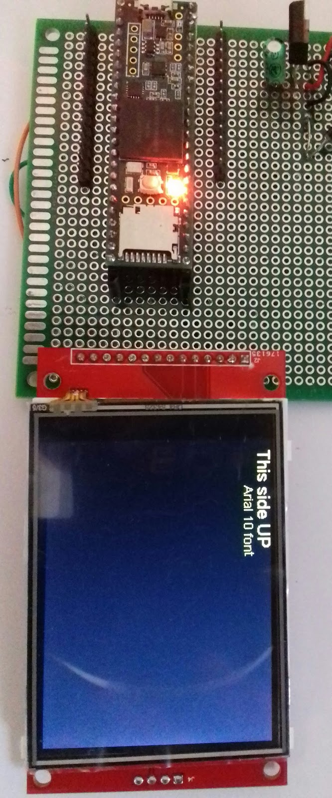
The display back side (top of the display as on previous picture is the sd card side)


The testing board with backside connections:


 Teensy 3.6 pin assignment diagram.


 Have a nice week!

Saturday, May 26, 2018

MIC5205 (LB30, KB30) Low noise regulator, increasing voltage output

Yes, made a mistake, ordered a mic5205 low noise regulator 3.0V output model, when I should had ordered the 3.3V version for a project in the "pipeline".

The typical application for the IC is like this:


This particular IC is not absolutely needed on the project but why not testing new devices....I should had read better the IC reference chart when ordered... should had been MIC5205-3.3BM5 instead of MIC5205-3.0BM5, as you can see, after the dash there's the output voltage, as on the data-sheet:


Looking at the internal diagram (fixed output version on top):

..it looks pretty much a "standard" series regulation schematic so there's room for change the output voltage and that can be done the following way:


By inserting a drop voltage from ground, at the IC GND pin, to a new ground it will "force" a "floating" ground at the anode of the 1N4007 diode, being the drop voltage value at the diode the increase in the schematic output. Any diode will work and depending of the forward voltage there will be the matching increase on the output. In my case the output is now 3.5  V from the original 3V, and that is inside the 2.6 to 3.6 V specs for the devices being powered by this IC downstream.

I'm really not a big fan of the SMD format since I don't have all the proper tools to solder them, anyhow since it's getting harder to get IC's in standard DIP format, in the future, will try to get more up-to-date on surface mount.
Here's a size, comparative to a resistor and the soldering iron tip.


I had to solder it with extra solder and then removed the excess with solder wick.  


Have a nice weekend!


Sunday, May 13, 2018

ADS-B In-line amplifier experiments and bias T for 1 Ghz

By Easter was in Portugal and got an in-line satellite amplifier since it covers the ADS-B frequency of 1090Mhz
The idea was to put it in service for the ADS-B receiver, improving reception

Without any proper quality equipment to verify the effectiveness, decide do use the QSpectrum analiser software and record the data for comparative analyses.
In the process also trimmed the antenna to different lengths...
ending up in around 7cm (6.8 should be the calculated exact size).

Testing was done inside so subject to nearby interferences and yes, the support is a broom stick...

Here's the experiment and results:
 Testing with just the cable, no power and the amplifier inline:

 Powering the amplifier and no antenna:

Amplifier on without antenna and smoothing 100nF cap on the power line to the amplifier:
 
 Here with 1pF as DC blocking capacitor on the bias T:

 Now, opening the balcony door on the living room (where I was experimenting) changed results:

 Now still with the open door and a 10pF cap blocking DC:

I closed the door and experimented with a 120pF capacitor:


Testing the antenna ground plane:
7cm with GP:
 

7cm no grGP:


Ground plane helps :)

Different antenna sizes:
14cm


13cm

12cm

8cm (different scale since approaching the expected length)

7cm


In the final configuration it improved reception from my previous experiences, still the antenna being in house only get's a max of 60miles/100Km coverage.


The bias T for the amp ended up as a simple 180pF dc blocking capacitor (C1) one RF choke and a smoothing capacitor. The value was selected as a low capacitive reactance at 1Ghz and a little higher at lower frequencies:

@ 1000 Mhz

    1 pF - 159    Ohm
100 pF -     1.59 Ohm
180 pf -      0.88 Ohm
100 nF -         1.59 E-3 Ohm

@ 100 Mhz

100 nF - 1.59 E-2 Ohm
180 pF - 8.8 Ohm

The implementation and schematic:


Only missing now is to enclose everything and place it on the roof.

Have fun!