Saturday, May 30, 2020

GPIB - HP 3478A multimeter

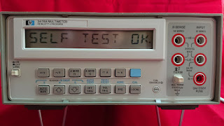
Another post for the GPIB series for an HP 3478 multimeter.


First code is how to display a string and then how to do a voltage readout.


Here's the code:

=== code begin

 #!/usr/bin/python
import time
import pyvisa
import sys

rm = pyvisa.ResourceManager()
inst = rm.open_resource('GPIB0::20::INSTR')


line = []
def count(instrument):

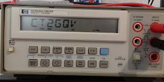
 output=inst.query("D2 CT2GQV")

 print "Set display to: CT2GQV",
# print output,

count(1)

=== code end

And the result:


If you want to read voltage (GPIB "F1" function) use the following code as example (no screenshot but similar to the code from previous posts series on GPIB), one version with graphical interface and another further bellow just from command line:

=== code start (graphical interface)
 #!/usr/bin/python
import Tkinter as tk
import pyvisa
import time

rm = pyvisa.ResourceManager()
# GPIB ID of my instrument is "20"
inst = rm.open_resource('GPIB0::20::INSTR')

counter = 0
def counter_label(label):
  def count():
    global counter
    counter += 1
    dcvolts=inst.query("F1")
    label.config(text=dcvolts+"V")
    label.after(1000, count)
  count()

root = tk.Tk()
root.title("HP 3478A DC Volts")
label = tk.Label(root, fg="light green", bg ="dark green", font = "Helvetica 18 bold italic")
label.pack()
counter_label(label)
button = tk.Button(root, text=' EXIT ', width=45, command=root.destroy)
button.pack()
root.mainloop()

=== code end

=== code start (read from command line)
#!/usr/bin/python
import time
import pyvisa
import sys

rm = pyvisa.ResourceManager()
inst = rm.open_resource('GPIB0::20::INSTR')


line = []
def count(instrument):

 output=inst.query("F1")

 print "DC Volts:",
 print output,

count(1)
=== code end

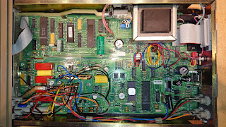
The multimeter inside look's like this:


Have a nice day!


Friday, May 15, 2020

World smallest spectrum analyzer


I think it's the smallest for sure. In regards to the spectrum analyzer, let's say it's more a band-scope...

Is it practical? No, it's just for fun since I have never seen a conversion of a Handycam CCD-F370E crt viewfinder into a spectrum analyzer, I've seen only simple oscilloscopes and small TV screens but never a total use of the two deflection coils in separate from the main viewfinder circuit.


 The only part left in place for the crt viewfinder was the beam/HV side, the two coils for the deflection were disconnected and connected to the circuit bellow:

In fact the hardest part was to find the correct settings for the yoke coils.
 Didn't included in the diagram is the RF part. For testing I used a normal receiver circuit and the signal level is taken from the audio and not trough a real logarithmic power meter. The vco was a simple varicap driven oscillator and feed with the sweep ramp signal, no blanking was used.

The video:


Here's during testing with a wide "video bandwidth" :


The beep/eared, and seen, is the Arduino VNA sweeping trough the band and the audio is from the receiver used as fronted.

The normal mess for the prototype, bellow the circuit with the sweep, vertical and horizontal yoke coil drivers:

Keep in mind that if you duplicate the circuit do swap the driver 2n3904/6 transistors with more powerful ones since they will get hot fast.

Out of curiosity I just realized that I disassemble this mini crt in 2012 and it had been getting dust to this day.

Have a nice day!


Monday, May 11, 2020

GPIB - Agilent/HP 6621A

A new one for the "software" pile, using GPIB, Linux and Python.

In the past I placed some example on how to control the outputs of the Agilent/HP 6621A using the Arduino USB to GPIB converter, now, using a "proper" GPIB board to get the current delivered on the two outputs in graphical form and from the command line to set the same outputs.


The code output, along with the startup icon on the background, bellow; "1" is the current of output one and "2" is for output #2:

...not much going around at the time of the display.

Since the voltage will not change in most of the testings I do I didn't included the set voltage, anyhow I have an external meter better suited for easy reading than the LCD on the equipment. The meter also includes output jacks extended from the back of the PSU unit.

The panel meter used was a "conversion" of a 0 to 250VAC type to 0 to 25VDC in this post.

The Code to display the output current (every 1s):

=== code start gpsu.py

#!/usr/bin/python
import Tkinter as tk
import pyvisa
import time

rm = pyvisa.ResourceManager()
inst = rm.open_resource('GPIB0::1::INSTR')

counter = 0
def counter_label(label):
  def count():
    global counter
    counter += 1
    current1=inst.query("IOUT?1")
    current2=inst.query("IOUT?2")
    label.config(text="1:"+current1+"2:"+current2)
    label.after(1000, count)
  count()

root = tk.Tk()
root.title("Agilent 6621A - Iout")
label = tk.Label(root, fg="light green", bg ="dark green", font = "Helvetica 18 bold italic")
label.pack()
counter_label(label)
button = tk.Button(root, text=' EXIT ', width=45, command=root.destroy)
button.pack()
root.mainloop()

=== code end gpsu.py


If you need to set output on the PSU from command prompt you can use this one bellow (setoutput.py):

=== code start setoutput.py

#!/usr/bin/python
# sets output 1 or 2 from Agilent 6621A power supply via gpib
# needs pyvisa
import time
import pyvisa
import sys

rm = pyvisa.ResourceManager()
# gpib card 0 address 1, change to your instrument address
inst = rm.open_resource('GPIB0::1::INSTR')

if len(sys.argv) == 3:
 print("Setting: ")
 print "Output #",
 print sys.argv[1],
 print "to ",
 print sys.argv[2],
 print " V"

 if sys.argv[1] == "1": # setting output number 1
  inst.query("VSET1,"+sys.argv[2])
  print("..done!")

 if sys.argv[1] == "2": # setting output number 2
  inst.query("VSET2,"+sys.argv[2])
  print("..done!")


# number of args not given currectly
else:
 print("")
 print("Not enough arguments")
 print("")
 print("setoutput.py ")
 print("")
 print("ex: setoutput.py 1 5.00")

# voltage2=inst.query("VOUT?2")
# current1=inst.query("IOUT?1")
# current2=inst.query("IOUT?2")

=== code end setoutput.py

To get all (current and voltage) from the PSU use the following code (getoutput.py):

(previous screenshot showing the output 1 and 2 voltages being set and the collected the current values along with the current)

=== code start getoutput.py

#!/usr/bin/python
# sets output 1 or 2 from Agilent 6621A power supply via gpib
# needs pyvisa
import time
import pyvisa
import sys

rm = pyvisa.ResourceManager()
# gpib card 0 address 1, change to your instrument address
inst = rm.open_resource('GPIB0::1::INSTR')

if len(sys.argv) == 3:
 print("Setting: ")
 print "Output #",
 print sys.argv[1],
 print "to ",
 print sys.argv[2],
 print " V"

 if sys.argv[1] == "1": # setting output number 1
  inst.query("VSET1,"+sys.argv[2])
  print("..done!")

 if sys.argv[1] == "2": # setting output number 2
  inst.query("VSET2,"+sys.argv[2])
  print("..done!")


# number of args not given currectly
else:
 print("")
 print("Not enough arguments")
 print("")
 print("setoutput.py ")
 print("")
 print("ex: setoutput.py 1 5.00")

# voltage2=inst.query("VOUT?2")
# current1=inst.query("IOUT?1")
# current2=inst.query("IOUT?2")

=== code end getoutput.py


Hope you find it useful.

Have a nice day!


Saturday, May 09, 2020

GPIB - HP 5316B Frequency Counter

Nothing fancy, here, just a way of getting a Linux python graphical interface for the output value of the HP5316B frequency counter on the GPIB interface.

Bellow example of code output/"display". Basic use will be video insertion during troubleshooting/recording and/or automated measurement.


The HP5316B frequency counter during testing of the Si5351 GPS disciplined oscillator with a NEO7M module from this post.


The icon on the desktop along with other projects for GPIB or serial interface data collection:


The ICS 4896 GPIB to serial converter (right icon) was describe on the previous post. The other ones to follow.


The Python code:

==== code start fcounter.py

import Tkinter as tk
import pyvisa
import time

rm = pyvisa.ResourceManager()
inst = rm.open_resource('GPIB0::3::INSTR')

counter = 0
def counter_label(label):
  def count():
    global counter
    counter += 1
    inst.write("FN1")
    result=inst.read_bytes(19, break_on_termchar='\r\n')
    result=result[2:] # renove the first 2 characters
    result=float(result)
    label.config(text=str(result)+" hz")
    label.after(2000, count)
  count()

root = tk.Tk()
root.title("   HP 5316B counter    ")
label = tk.Label(root, fg="light green", bg ="dark green", font = "Helvetica 18 bold italic")
label.pack()
counter_label(label)
button = tk.Button(root, text=' EXIT ', width=35, command=root.destroy)
button.pack()
root.mainloop(

==== end code fcounter.py

You will need to set the GPIB address for your instrument on the following line:
inst = rm.open_resource('GPIB0::3::INSTR')
In my case it's address "3".

If you are using Linux Mint the desktop icon/launcher code this bellow. You need do adapt to your specific directories.

==== launcher

[Desktop Entry]
Name=HP5316B
Exec=python /home/rmartins/soft/fcounter/fcounter.py
Comment=
Terminal=false
Icon=/home/rmartins/soft/fcounter/th.jpeg
Type=Application

==== end launcher


Have a great day!

Sunday, May 03, 2020

GPIB - using the ICS 4896

You can get one of this devices out of the usual "junk" site for around 60 Eur, pretty useless if you think you can use it a a serial to GPIB because it's only a "collector" of 4 serial interfaces and placing the data on a GPIB bus. You will be better suited for the same with a regular dual or quad serial card or even the usb to serial adapters unless you already have a GPIB interface card.

I got one unit thinking that eventual I could use it also as a converter/interface of serial to GPIB, no, I should have read the specs first! Anyhow might be useful eventually one day to get multiple serial data simultaneously on the GPIB bus.

Reference picture of the device:


This was also the device that took me more time to make it work with the National Instruments GPIP board from this post on Linux.

The main code/graphical interface in python is this one (getICS4896S1.py):

=========
 #!/usr/bin/python
import Tkinter as tk
import time
import Gpib
import subprocess
inst = Gpib.Gpib("ics")

counter = 0
line = []

def counter_label(label):
  def count():
    global counter
    counter += 1
    p = subprocess.Popen("/home/rmartins/soft/ics_serial/getonelineS1.py", stdout=subprocess.PIPE, shell=True)
    (output, err) = p.communicate()
    p_status = p.wait()
    label.config(text=output)
    label.after(100, count)
  count()


root = tk.Tk()
root.title("    ICS 4896 reading from S1    ")
label = tk.Label(root, fg="green")
label.pack()
counter_label(label)
button = tk.Button(root, text='Stop', width=45, command=root.destroy)
button.pack()
root.mainloop()
=========

It will call the following script (/home/rmartins/soft/ics_serial/getonelineS1.py) to get one line from the first serial:

=========
#!/usr/bin/python
import time
import Gpib
import sys
inst = Gpib.Gpib("ics")
exception = 0

line = []
def count(instrument):
    global exception
    try:
     result = inst.read(1)
     if result == "\n":
      print(''.join(line))
      exception = 1
      return exception
     else:
      line.append(result)      
    except: expection = 2
while True:
 if exception == 1: exit()
 count(1)

=========

The "ics" instrument definition used on the previous code is this one on /usr/local/etc/gpib.conf:

=========
device {
        minor = 0       /* minor number for interface board this device is connected to */
        name = "ics"    /* device mnemonic */
        pad = 4         /* The Primary GPIB Address */
        sad = 97        /* Secondary Address for Serial 1 */

        eos = 0xa       /* EOS Byte */
        set-reos = no /* Terminate read if EOS */
        set-bin = no /* Compare EOS 8-bit */
}


=========


Here's an example output of the code on the top window and "minicom" on lower window, computer serial (with minicom) connected to the first serial on the ICS 4896 where I wrote the string "10.002E-2V" to appear on the ICS device:


 You could do similar on command line using "ibterm" (from gpib Linux driver package)


Hope it helps.

Have fun!