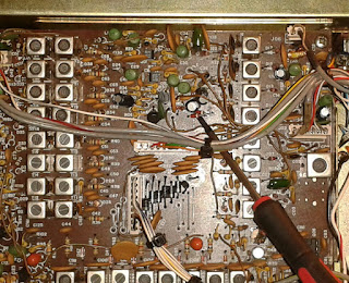
This one was not obvious for me, still isn't completely understood, only fixed, one of the reasons for not "getting there" faster was I was also having low to none output on 20m, so was suspecting something on the bandpass filters or the associated switching circuit. The filter weren't making much sense because reception was good...it had to be something else.
As soon as I figure out that low output on 20m was due to improper bandpass tune it become obvious which way to go for finding the actual issue.
This is the board in question and the problem is around there...(RF unit PB2093b) !:
Somewhere...:
So what I did was disconnecting the output to the PA and place the scope to check for the level before amplification, after "tuning" the 20m band filter only no power on 12 , 17 and 30m band... so what is common between the bands and only on the TX circuit if I excluded the filters?:
So it was starting to be obvious that the issue was with the associate circuit of Q04, started measuring on the anode of D20 and noticed the bias was smaller every time I selected 12, 17 or 30m band and keyed the transmitter, the bias is also dependent on TX 13.8 (pin 3) from J02 plug, so for each test transmitting must be done. The only cause of smaller bias can only be diodes D21, D71 and D72, impossible for 3 diodes to be out of spec/broken at the same time and since the voltage droped they were for sure working (an open diode would keep the bias high and a short one very low, was not the case in either). So I lifted the diodes and voila', everything back to life. I'm sure the actual "fault" is somewere else, measured R06 and is spot on so could be any of the other parts. As soon as I have patience and more time will try to dig furter.
I think Yaesu might have placed the 3 diodes in the circuit after checking that probably some bands had excessive power and that as a way to limit a little on the output since the diodes will drop the bias lower and the series of D20 with the PN junction from base to emitter, at the moment I see no other reason for the use of the diodes there and only on these 3 bands, it should not be curing any instability since the band's are not even sequential....
Here the "offending" diodes lifted?
And already outputing some power into a dummy load with the watt-meter in the 15W scale and the carrier control fully counter-clockwise (low output).
..I will leave as it is for now, at least this unit I can consider as fully operational....
On to the next unit, the blue light one!
Have a nice weekend!


No comments:
Post a Comment