I'm now in holidays in Portugal and finally could see the Sommerkamp FT-307 (Yesu FT-107) I bough last time. If you don't know the story, bough a non working unit/unknown status some time ago and asked a friend to collect and keep it until my return.
Well, the radio is as was advertised, non transmitting and not tested after some smoke left the equipment during transmit.
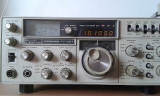
I powered it on as soon as received the equipment and it's OK receiving but no transmission. Here's the first pictures:

Now, the equipment was set up to use 220v on the internal power supply, currently mains is at 230V so I needed to make the changes before continuing testing.
I was surprised how easy was to make the change, that is working inside the radio, here's the process:
1- Remove the top cover (you need to remove the handle bolts also), no picture since I'm sure everybody already did this to a radio at some point in time.
This step is only needed as a helper to check the internal routing of the cables on re-assembly.
2- Remove the 6 bolts from the back cover:
 3- After the cover removed, remove the 4 fixing bolts from the PSU unit to the chassis:

 4 - ...then gently pull the PSU unit and remove the 4 bolts securing the gridded top cover to expose the connections:
 5- Previous picture shows the 220V connection... next one already with connection on 234/230:

... that's it, two solder points changed, one is the "jumper" and the other the "line" both from 110 to 117.
Additional notes: the diagram and the vcc as measured on the radio meter:


Have a nice week!
Well, the radio is as was advertised, non transmitting and not tested after some smoke left the equipment during transmit.
I powered it on as soon as received the equipment and it's OK receiving but no transmission. Here's the first pictures:


Now, the equipment was set up to use 220v on the internal power supply, currently mains is at 230V so I needed to make the changes before continuing testing.
I was surprised how easy was to make the change, that is working inside the radio, here's the process:
1- Remove the top cover (you need to remove the handle bolts also), no picture since I'm sure everybody already did this to a radio at some point in time.
This step is only needed as a helper to check the internal routing of the cables on re-assembly.
2- Remove the 6 bolts from the back cover:


... that's it, two solder points changed, one is the "jumper" and the other the "line" both from 110 to 117.
Additional notes: the diagram and the vcc as measured on the radio meter:


Have a nice week!


