This will be part of a series for test instrument remote control, I started this with my own "instrument" design and code a USB temperature measurement on this blog post and bellow hardware:

This time and because I have several branded instruments with GPIB bus control, decided to try this nice project that consist of an Arduino connected to a GPIB plug and acting as a poor man GPIB controller.
The idea of the original project was to create an affordable alternative to more expensive solution of USB to GPIB, PCMCIA or even PCI GPIB cards that still a bit on the expensive side for the common amateur.
Basically only had to follow the instructions on the project page, I used an GPIB cable cut in half since it was cheaper than just buying the plugs and can still make a second unit with the half left:

... I chose to label all the cables to pin numbers to keep it easy, otherwise I could had messed up. The cabling stayed a bit squeezed because I under estimated the box size needed.
 Used a 1.5m GPIB instrument cable with plugs in both ends.
Another view of the "mess":

For the usage of the system, bellow an example with the Agilent 6621A power supply on GPIB address 1:
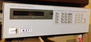
 Basically, you set the GPIB instrument address (you want to comunicate with) with "++addr" in my case the power supply is set to 1, then you set output 1 to 5 volts (VSET1,5) and then "ask" the instrument to read the output 1 value (VOUT?1 and ++read). The 9.99v on the image was the output of a previous testing setting to 10V.
For the configuration of the USB port and output I get on a Linux system it's like this:
 115200 baud 8N1, in my case the device is loaded under /dev/ttyACM0
I had some testing with other Instruments:
R & S NRVS power meter:
 Marconi 6960A power meter:

Besides the number of pins to connect from the GPIB plug to the Arduino the hardest part is going trough the instruments GPIB programing manual and trying to check which of the commands work. Interesting enough the one that should be standard; get instrument id (ID?) I never got and answer using this board when testing.
Right now this project is a backup option/solution because I manage to get a very cheap PCI32 GPIB card and am using it at the moment. I will provide some more info on that on the future.
Have a nice day and stay safe!

This time and because I have several branded instruments with GPIB bus control, decided to try this nice project that consist of an Arduino connected to a GPIB plug and acting as a poor man GPIB controller.
The idea of the original project was to create an affordable alternative to more expensive solution of USB to GPIB, PCMCIA or even PCI GPIB cards that still a bit on the expensive side for the common amateur.
Basically only had to follow the instructions on the project page, I used an GPIB cable cut in half since it was cheaper than just buying the plugs and can still make a second unit with the half left:

... I chose to label all the cables to pin numbers to keep it easy, otherwise I could had messed up. The cabling stayed a bit squeezed because I under estimated the box size needed.

Another view of the "mess":

For the usage of the system, bellow an example with the Agilent 6621A power supply on GPIB address 1:


For the configuration of the USB port and output I get on a Linux system it's like this:

I had some testing with other Instruments:
R & S NRVS power meter:


Besides the number of pins to connect from the GPIB plug to the Arduino the hardest part is going trough the instruments GPIB programing manual and trying to check which of the commands work. Interesting enough the one that should be standard; get instrument id (ID?) I never got and answer using this board when testing.
Right now this project is a backup option/solution because I manage to get a very cheap PCI32 GPIB card and am using it at the moment. I will provide some more info on that on the future.
Have a nice day and stay safe!