Recently I acquired a Commtel COM205 scanner, for Europe, that is the same as a Realistic PRO 2006 in other parts of the world.

The idea is to use the discriminator out to make a simple deviation meter.
While I bough it second hand I made sure it had the EL backlight was still working and strong just because they have a tendency to fail or dim and I didn't want to install a new one.
Upon receiving, the light only worked for a brief second, immediately I imagine it had failed somehow during transit.
Started to troubleshoot and at some point was convinced it was the high voltage powering circuit that filed because it looked like a very low voltage to power an EL panel (55V) when I was expected thinking that would be in the undred.
After some pocking and even replacing one of the capacitors in the oscillator circuit that generates the high voltage that I realized that was a bad contact on the EL terminals. Good, no more troubleshooting. Anyhow used the occasion to clean some soldering job from previous owner and now it's working as it should.

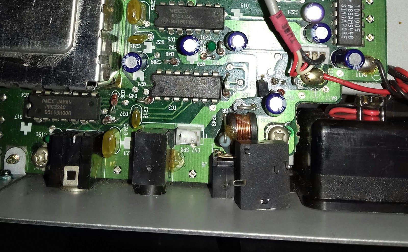
The back light circuit along with my measurement:
 I suspect that if ever fails it will be wither C506 or Q508
The EL panel voltage can be measured at the two terminal above T501 (upper right corner):

If you need to change the EL panel, there's a nice description of the process here. I suspect that replacing with LED will be valid also but there's not much space to place them, maybe a led strip would do the job. You only need the back light for visibility in low light conditions (during the night), during the day it's readable without it.
I used the fact that the box was open from the previous job to include the discriminator out plug and the connection to the test point.
The operation is simple and better detailed from this external post.
My job:
The jack fitted above the DC input:

The inside of the jack:
 Connection to the test point TP2 (a vertical resistor):
 then a series 12K resistor and a parallel to ground 2.2nF capacitor (I had to parallel 2*1nF).
Another view:
 On the output of the jack these are the values obtained (DC and AC):


...now I need to finish the deviation meter.
Have a nice day!

The idea is to use the discriminator out to make a simple deviation meter.
While I bough it second hand I made sure it had the EL backlight was still working and strong just because they have a tendency to fail or dim and I didn't want to install a new one.
Upon receiving, the light only worked for a brief second, immediately I imagine it had failed somehow during transit.
Started to troubleshoot and at some point was convinced it was the high voltage powering circuit that filed because it looked like a very low voltage to power an EL panel (55V) when I was expected thinking that would be in the undred.
After some pocking and even replacing one of the capacitors in the oscillator circuit that generates the high voltage that I realized that was a bad contact on the EL terminals. Good, no more troubleshooting. Anyhow used the occasion to clean some soldering job from previous owner and now it's working as it should.

The back light circuit along with my measurement:

The EL panel voltage can be measured at the two terminal above T501 (upper right corner):

If you need to change the EL panel, there's a nice description of the process here. I suspect that replacing with LED will be valid also but there's not much space to place them, maybe a led strip would do the job. You only need the back light for visibility in low light conditions (during the night), during the day it's readable without it.
I used the fact that the box was open from the previous job to include the discriminator out plug and the connection to the test point.
The operation is simple and better detailed from this external post.
My job:
The jack fitted above the DC input:

The inside of the jack:

Another view:


...now I need to finish the deviation meter.
Have a nice day!
1 comment:
Great job. The Realistic Pro 2006 is an excellent radio and was worth the fix.
Post a Comment