Friday, February 26, 2010

Mixing, not RF, DNA

Now it's time to slow down a little bit on the blog, I have other immediate priorities as you can see in the photo.
All went well and the little girl is healthy!


I was trying to finish the hf radio before the birth but could only finish the balanced modulator and the 9Mhz filter preamp. To do are: the output mixer and the HF PA.

Mic preamp and balanced modulator (from right to left):


Crystal filter preamp (not yet finished in this photo):


Here's the schematics:


The crystal filter part is not yet tested....use at your own risk...as allways!


Monday, February 22, 2010

Thunderstorm

....I had been some time ago in the sea in heavy thunderstorm, no problem with that, when you listen to the thunder means that it didn't hit you!
Today the local forecast was for some lightning activity so for precaution I removed the antenna cables entering the shack.
I made some time ago a small peace of metal with pass-true "PL" plugs so I can disconnect the antennas without going to the back of the radios.

I did disconnect the antennas and was checking the stock on some components that were missing when a really big thunder hit some near place. Can't recall the last time I jumped of a chair.... anyhow time to leave the shack and disconnect the soldering iron before some really bad thing happens.


I was doing some soldering on the balanced modulator and mic amplifier for the transmission part on the hf radio. Will post progress soon.

Looks like that everyone that has a shack also owns a cat (or the cat owns you).... here's mine:


Yes, the cat is right, in days like this you should not leave your bed!

Saturday, February 20, 2010

14.058 Mhz FM IF TX - overtone at 28Mhz

Another test for the 144Mhz FM transmiter. This time I tested an oscillator/modulator with an CD4069 (6 inverter ports on one package)
Sounds promising....


The schematic:


I used the "modulator" from SM0VPO QRP FM TX that connects to the BB109 varicap (on the above shcmatic) with an 10nF cap in the middle:


The cristal was on the junk box, I bough 40 diferent crystals in last ham radio fair, so plenty of them to test. This one came from a scanner receiver I think, judging from the marks on it (73.675 RX). If I am not satisfied since it oscilates on 14.058 Mhz could be used for my S9 signal generator.

Beeing the output at the 10m band it should be easy to make an up converter and do some filtering. Unfortunatly the FM part starts a litle big higger in frequency, else the schematic could double as 10m and 2m FM :)

Thursday, February 18, 2010

10.7 Mhz FM IF TX - Mixed to 144Mhz


I decided I was not waiting for some 10.7Mhz IF cans to test the "rig", so placed a small "can" (KANK3335) in the colector of the second transistor and the "can" output to an SBL-1 mixer, then connected the Si570 vfo to the IF input on the mixer and the output to a small peace of wire near the TM-D700 antenna. Here we go! We have RF!!! Don't have a spectrum analyser but sure it should not be a beautiful sight in the RF output....

In the first "on air" test I was a little out of frequency, corrected that but the camera stop filming ("no space left on device" for those o know the meaning....), anyhow it neds a lot of filtering and a lot of improvement on the modulator side (stability). When I decide to finish this and give the project a box probably will not use the SBL-1 (will use original design) and will be putting the frequency rock bound since I almost ever use the local repeater or make qso's in VHF.
The microphone section needs to be corrected and properly adjusted. If I speak to close I have some distortion, if far away I listem to my own voice and can't make a correct judgement on quality. Probably will put some headphones and record several transmissions...on 10.7Mhz :) For sure there are some precise testing procedure for mudlation adjust, will investigate if there are any "tuna tin" or "Altoids" project on the subject.
The video, isn't it beautifull when something actuali work.... kind of...:

Wednesday, February 17, 2010

10.something Mhz FM tx -2


I decided I will finish this 144Mhz transmitter instead of making another pcb to the junk pile.

Have tree choices:

1 - Make a variable modulator in the range 10.2 - 11.2 and mix with 136Mhz (crystal oscillator) to get the desired 144/145 range.

2 - Make a fixed modulator at 10.7Mhz and use the si570 kit to put the frequency on the right spot.

3 - Make a fixed modulator at 10.1Mhz (10.7 - 600Khz repeater shift) and use a cristal oscilator at 136Mhz that can give reception using 10.7Mhz IF and transmitting using the 10.1Mhz IF

...decisions...decisions...

Mean while I am placing the tests on a more acceptable board has you can see in the photo.
Since I had none available 10.7Mhz IF transformer I decided to brew one, it's on the bottom right part of the picture, in the left is the coil former type used (can't recall the correct name in English; checked in the dictionary, it's "plastic bushes").
Honestly I still don't know if it works since I spent 1 hour trying to find why the circuit stopped working.....after all it was a broken ground cable at mic input plug.... arrrghhh! Maybe tomorrow I can say more about the homebrew if transformer.

Monday, February 15, 2010

10.something Mhz FM tx


Following some emails exchanged with CT5JZX about an possible VHF FM transmitter he will build I decide to give a little try on FM tx... My last attempt was about probably 20 years ago when I built an broadcast band transmitter enough to give music to all my neighbours.

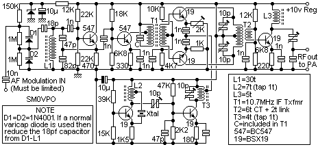
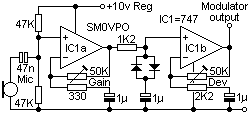
This was just the IF part of a possible transmiter I will build one of this days... FM modulation is via 2 1N4001 diodes working as varicaps, mic preamp is an LM741, the mic is the one from last post here on the blog. Since I didn't have any 10.7 Mhz IF transformer for the coil I brew one just for testing with 20 turns on a red core (no calculation, I just figure it would be around 20 turns, came out as 10.9Mhz, nice). I tryed an 10.7Mhz cristal but without success using 1N4001 as varicap, also tried an 10.7 ceramic filter as oscilator with limited sucess, probably in the future will try again with a cristal for stabilty porpose. The original design is with an coil.
The output of the oscilator connects to a capacitor and then to the frequency counter, the ferrite coil on the righ is the pick up coil inserted on that capacitor and connected to the antenna input, enough to give S9+Full scale on my receiver..... problem is it must be well filtered because there's a lot of harmonic energy at the second harmonic....

Eventually a schematic will be post here as soon as I draw it, basicaly is a design by Harry SM0VPO with only minor component changes. In the video I didn't adjusted the deviation and level pot and didn't let the oscillator warm up a litle, with the right coil I think it will be quite stable, suficient to make a transmiter.
Another project that will have to wait a itle bit.
Here the first test, I was receiving a litle bit out of the oscilator frequency:


Schematic is part of this (only made fron the left of the circuit to the first BC547 transistor, the oscilator, and the 1n cap were I connected the freq. counter). Power supply is 9v, didn't know what the value of the zener was, probabli 6.8v, but works ok with 9v, removed the 12k fron the schematic.


Modulation from this:


Didn't had the 747 so used 2 LM741 (one LM and one uA), one of the 50K pot was done with an 100K parale with an 100K resistor. Didn't had at the moment 47K resistors so used 56K for the voltage divider in the first opamp. Power supply used is again 9v.
Original work is from: http://www.sm0vpo.com/

Friday, February 12, 2010

HF radio (7) - Microphone


Continuing with the hf radio! Now the transmitting section, let's start from the microphone. Some time ago I managed to buy an table top microphone, not that I didn't had any other one but because it was indeed very cheap. For use with the hf radio it was as simple mater of changing the inner connections to what I wanted: One terminal to the "live" microphone capsule, one for the PTT, both sharing a common ground. Transmission is accomplished by shorting the ptt terminal to ground. Microphone capsule is allways connected so I can use vox.
No big magic here, only sinple switch identification and small changes on the mic/switch board since it had some resitors an capacitor making a DC blocking filter.