Not much time for shack work but today was a local holiday so decided to build something.
Well, continuing, the circuit bellow is not exactly a loop but an FM tx and FM rx connected without antenna....
I had to test true FM modulation (without multiplication and on "low" frequencies) using an crystal or coil and test FM detection using an NE602, so latched up two simple circuits and connected them back to back.

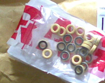
Took me some time to find in the "junk yard" a suitable 10.7Mhz IF transformer/coil. Most I found were for 455Khz but luckily in an old car radio there were two (the green and the orange in the picture). I could use the green coil also for FM tx but in this first test I used a 10.7 crystal for the FM carrier, I wanted a more stable source.
Transmit part is from SM0VPO: http://www.sm0vpo.com/tx/fm-tx1.htm
I just used the modulation part until the first BC547 (I used an 2n2222) and then a simple buffer before injecting the signal on the NE602 part.
The receiving end is from KF5OBS: http://jaunty-electronics.com/blog/2012/08/no-tune-ne602-ne612-fm-demodulator/
I scaled the circuit (more or less) to 10.7, removed the input amp and placed a simple trim-pot attenuator, input from the bufer output on the tx part.
Audio amp is one general purpose class AB with discrete components. A simple LM386 would to the same job, just had this one at hand.
Audio is still not perfect on both TX and RX but quit understandable. More tweaking is needed specially in the TX part. Anyhow this is just a concept, I will test other simple circuits that could be handy for adding FM to the "Speaky".
Meanwhile I "prepared" 2 more band modules for the "Speaky" but still have to wait for some T37-2 toroids to arrive for the bandpass and oscillator parts... see bellow on the assembled module the wood toroid for the VFO part.
Have a nice day!