Sunday, January 20, 2013

A special QSO


I had said to myself, long time ago, that I would only consider myself an reasonable amateur if I managed to build and make a QSO with something I built instead of using an appliance. I don't say all ham's should follow my idea, each one should have is own goals.


Keeping short, some time ago I built an VHF FM transceiver (with some small parts designed by me on the reception chain) and made at least 2 QSO's... before reusing some components to another project (a VHF crystal controlled transmitter, unfinished so far). It was a nice feeling of accomplishment but I wanted to make also a QSO in the HF bands using something soldered my me.


Last Friday I was doing some adjustment in the "Speaky" transceiver BFO and band pass filter for the 17m band when I heard someone CQ'ing, I couldn't resist and answered the call, first a brief "QRZ" and finally LX1HD (1600Km from my QTH) managed to decode my call-sign... YES!!! I was so nervous like it was my first ever QSO because I still didn't placed the heath dissipator on the final transistors and they are somehow expensive, kept the QSO very short and asked for an audio report, Henri answered stating some RF present in the signal which latter traced to the audio compression part. I thanked a lot to Henri and said goodbye because I was very afraid of blowing the finals.  Think I even didn't sent Henri his signal report but was at least 59....the s-meter isn't calibrated yet as so is the output power meter...!


 Here it is as when QSO was made:
 Bench testing the unit:


Now some things to do before closing the top lid and have fun QSO'ing:

Add heat dissipation to the final transistors.
Check audio compression/gain issue
Trim PA bias
Calibrate internal power/S-meter
Tighten cables.
Optimize IF filter bandwidth, now its a little wide for my taste.
Rebuild 40m bandpass filter, it works but trimmers are on the lowest capacity setting.
Add 20, 15 and 10m band....


 ...Maybe my next objective could be someday design an built everything from the ground up....maybe

Have a nice week!


Thursday, January 17, 2013

4 mistakes


Considering the sheer amount of connections and components I wasn't expecting 0 errors building the kit.... but from what I found so far none made were critical to the transceiver function. Here's the mistakes description:


* Frequency on the frequency counter: I was getting strange behavior from the frequency counter, the frequency was offset for some 500Khz, if it was by the IF frequency I could suspect on mixing effects or something, but 500Khz?... I finally thought it should be the code on the PIC, started to look around and guess what, the supposed 4Mhz clock crystal for the PIC was an 8Mhz one, how this happened I don't know but it's probable that an 8Mhz crystal came with the kit instead of the 4Mhz one. Replaced and now it's spot on.


* IF gain control: Was counterclockwise increasing, changed to "standard" settings.
 
* Drive power/RF output control: Was counterclockwise increasing, changed to "standard" settings.

* 40m bandpass filter: Not actually an error, it was working from the beginning but with marginal settings so will try to improve a little bit, anyhow can now listen to CT and EA stations with just 2m of wire connected to the "Speaky" antenna terminal inside the shack.

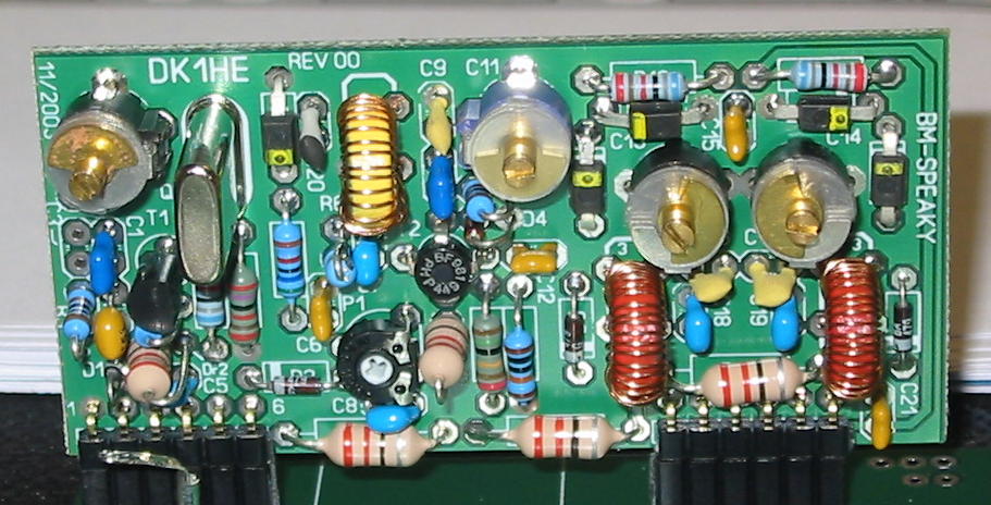
Now some photos on the "Speaky" parts:

40m band module:
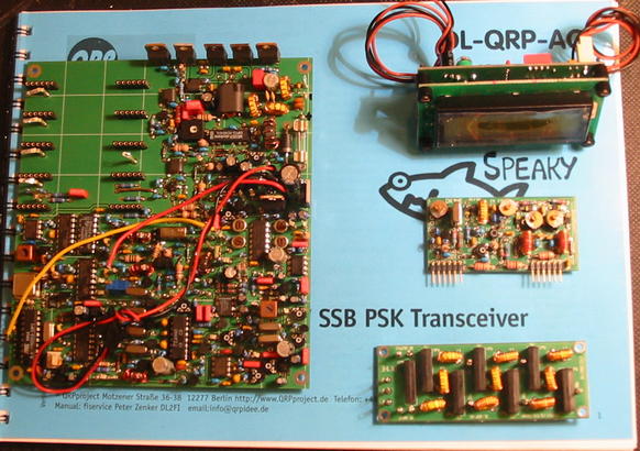
Main board, frequency counter, band module, low pass filters:


Next steps:

* Finishing the 17m band module 

* Testing the first transmission


Have reception on the 17m band, have transmission audio and RF power but it was just a quick test, I have to tune all the transmission path settings first.

See you!


Monday, January 14, 2013

My new rig...

My first rig was a Kenwood TS-50, at that time it wasn't cheap but it was the cheaper rig in the market (new). It has been serving me nice and I still own it.

Now, after learning a little bit more about the hobby, made me realize I needed something different....


OK, I know, it's probably a little on the expensive side but think about the joy of operating this little rig, and when you made a QSO you can tell with all the pride the model of your equipment and talk about all the bells and whistles, you can even mention it can make tea and toasts...

 It's for sure a pileup breaker...besides the bank account...


So without more delays....


....here it is....

....my new rig after the first successful real air transmission copy on 40m band...
It was with about 1m of wire connected directly to the first mixer amp since I haven't found yet the issue in the bandpass filter or in the 33Mhz low pass part (another possible candidate for the problem)....

(an old photo but same model)


Will keep debugging the next few days but at least half the rig works!!! I'm happy!

Saturday, January 12, 2013

Hot tip

..Ok, I fixed the soldering iron heater, eg: bought a new one, for the price I could have bought 4 cheap soldering irons but probably would not last the same time so I stick with this one since I'm already used to shape and size.

After getting again some heath from the soldering tip I finished re-cabling the Speaky, minus the external cw key but will solder those 3 wires in a near future.


Also a better cable routing will be finished after getting this QRP "beast" to full working condition :)


I powered it on and kind of worked..... have noise, good! Had a little problem in the frequency display, I programed it wrongly and the most interesting/strange stuff is when I disconnect the counter signal input the radio enters TX mode. I changed nothing and now it's OK on that issue but now sometimes it doesn't count....go figure, not critical for now I'm measuring VFO frequency with my external frequency counter....

All controls work but can't see much change from the pre-selector, more on this latter.
Here's an idea on the parts involved:


I can receive an 8 Mhz (the IF) signal from the frequency generator and a big signal on the 40m band (the only band module connected for now) transmitted from the FT-817 to a dummy load, still real air transmission got none so far. Will have to debug but I'm thinking that could be an issue from the bandpass filter or the first rf amp part before the first mixer, more debug on the next days....
Didn't checked transmission part so far.

Here's a global view of the receive part:


Have a nice weekend...

Tuesday, January 08, 2013

Cold heather


Yesterday I notice the soldering iron getting cold, immediately checked mains power (just looked at the soldering table light) and then I thought maybe the cable entering the iron handle got broken, twisted it a little bit and looked like the problem was over.... today I continued re-cablling the "Speaky" and at some point the soldering iron got cold again, this time it didn't resuscitate....

...and yes I checked continuity on the element...open!
 It was a "good" friend for over 8 years...now I have to buy a replacement heather element which is roughly half the price of a new iron....


...and you still have to have another iron to solder the new element.

One thing that is lasting less than expected was the new tip I bought two years ago

the original one and the one afterward lasted much lounger, probably their reducing manufacturing costs or outsourcing...


Saturday, January 05, 2013

Speaky re-cabling

Built once....building twice!

Was not happy with cables on the first try so will go for round two, this is a major task since none of the external parts fix directly to the main board...

I suspect that a lot of debug will have to be made afterwards since it's easy to fail somewhere along the path and the "Speaky" it's a very big project.

The blue color cables are all new, now they have enough length and will allow me to push back the front panel for main board inspection and debugging.
 ...meanwhile I broke the pre-selector pot. Can you believe that both electronics shop in town don't have the 10K linear value en stock?

Not doing it fast and not a priority for sure but I would like to finish the kit during this century.

Have a nice weekend!


Wednesday, January 02, 2013

VFO wave


I decided to have a closer "look" on the 1972, 73 magazine VFO circuit from a previous post.

The circuit (minus the red part):

The setup:

 ..coil is from an old IF transformer and the tank cap was the first on hand...
turns out it oscillates at:

 ..Khz

Now the output wave with "post processing" markers...:

 ...period is almost one division (10uS).
it's not a perfect sine even when "stretched":

 ...almost 8uS of period (4 divisions), that translates to 125Khz, close to the measured 137Khz (7.3uS), a normal error due to optical and timebase factor..

...will try other oscillator circuits in the future searching for the perfect wave....

Have a great 2013!