Monday, February 13, 2012

World Radio Day

Today it's "World Radio Day" by UNESCO.

It's more Broadcast than Ham related but never the less both mix at some point!

More info here:

http://www.unesco.org/new/en/communication-and-information/events/prizes-and-celebrations/celebrations/world-radio-day/

Here's a list of some important dates for radio from the Unesco site:

".....22 February 1857 : Birthday of Heinrich Rudolf Hertz, a German physicist who clarified and expanded the electromagnetic theory of light that had been put forth by Maxwell. He was the first to satisfactorily demonstrate the existence of electromagnetic waves by building an apparatus to produce and detect radio waves. His achievements triggered the invention of the wireless telegraph and radio.
30 November 1858 : Birthday of Jagdish Chandra Bose, a pioneer of wireless broadcasting. Indian physicist, biologist, and early writer of science fiction, he pioneered the investigation of radio and microwave optics and laid the foundations of experimental science in the Indian subcontinent.
6 October 1866 : Birthday of Reginald Fessenden, inventor of audio broadcasting and radio pioneer.
25 April 1874 : Marconi’s date of birth.
7 May 1895 : Russian inventor Alexander Popov’s first demonstration of his radio receiver to the Russian Physical and Chemical Society. The date is celebrated in the Russian Federation and Bulgaria as "Radio Day".
28 March 1896 : Anniversary of Marconi's first audio transmission. (Marconi is known for his development of the telegraph and we have found no evidence of a first in audio transmissions).
2 June 1896 : Marconi patented a radio device.
27 July 1896 : Marconi's first public wireless transmission of Morse code....."

Have a nice week!

Phone call

Last Friday night got a phone call from a friend:

(F: friend)
(M: me)

M: Hello
F: Look, the name Yaesu-Musen tell's you something
M: Yes
F: The number FT-7 tell's you something?
M: Yes, it's a qrp I think
F: And the markings: FL-110
M: Hum, I think it's a linear to match the FT-7
F: I have here this equipment, do you want to have a look?
M: How did you get those?
F: Never mind!
M: Are you at home tomorrow?
F: No, will be out.
M: Just wait there! I will have diner latter!

My friend isn't a radio amateur so I drove to see what he was up to.
A friend of him who is/was (giving up) radio amateur gave him this equipments and he handled to me for testing.

Saturday morning I went to the sack so I could test both equipments.
The FT-7 isn't esthetically perfect (althoug the mic is) but the FL-110 look's like it was never used. They came in the original box but only one power cable so will test the FL-110 against the TS-50 on 10w out.


After powering up the FT-7 I started to get some interference in audio, I thought immediately that there was a problem with the radio but later the TS-50 was with the same, so it was due to band conditions. I did got some signals on 20m but then audio started to fade away (on the FT-7) so the radio has some problem for sure.
Then I disconnected the FT-7 and connected the FL-110 to the TS-50. Power up, and it lit the normal LED. Transmission test.... zip, nothing, nada, not even the operate LED, I switched to AM to get a bigger carrier to activate the RF switch, nothing....now I have to test with the external activated switch but I think there's some problem internally.

Conclusion, two inoperative equipments...for now... I told last Friday to my friend that we will put the equipment at his home, connect an antenna and let him decide to make the ham radio exam. He told me he was going to think about it, I understand he's position, I guess he is a little fed up of radios, he's an air traffic controller!

Saturday, February 11, 2012

AM for the "BITX"

Nothing more simple than adding AM reception to the BITX transceiver, Right?

I was over confidence on this one, having done SSB I thought AM was going to be child's play..... a simple rectifying diode, a low-pass filter and that's it! I missed something in between for sure!
Was getting nothing at all, getting a whistle or getting to low sound...so after some days testing and a lot of soldering after I came up to my first acceptable version....oh did I mentioned that the idea was to use only the same values of components of the BITX V3 design? NO? Yes, that was the idea, even so I had to use 9 different values of resistors, diodes and caps (all standard values and no IC's or coils) but I also added airband reception in between except I'm using an external VFO. If the 2SC2570 can be used as VHF oscillator then the count will stay at 9....will try that in the future (7 for the AM part and 2 for the airband input filter).

Since this is the first working test, no schematic will be provided, I need to improve a little bit and try to reduce the number of different components.

Here's the lousy video, live audio was greater than the one captured on mic, I guess that if my mobile phone was a toaster all would came out burned!
Not all the components you see in the video are part of the design :)


Have a nice weekend!

Wednesday, February 01, 2012

It's a BITX...

...Not to take literally....

Some time ago I used parts of the "bitx" transceiver for a small receiver, mainly the first mixer and the crystal filter, for the SSB demodulator and audio I used the NE602/LM741/LM386 combination, it worked good but never finished it (at least give it a decent box).
Now decided to use some this parts (all the RF receiving strip) for a NAVTEX receiver since I found in the crystal box one that oscilates around 9.510 Mhz... so with more 490Khz (one of NAVTEX frequencies) and it sits in the middle of "bitx" IF (10Mhz). Since I was building basically all the receiver part why not make a full version, so here part of the build process...

First tests using the ADE-1 mixer:
Now fast forward and some soldering....bellow image from top to bottom upright pcb's the 9.5Mhz oscillator the 4Mhz vfo (horizontally laid) and the 10Mhz BFO (with LSB/USB, two white variable caps)


I add already build last time the first mixer with diodes but now decided to use an ADE-1 mixer, also for the SSB demodulator one was used.

The first problem was in the audio stage... supposedly the easiest part, I was getting smoke in one of the limiting resistors, luck (and experience) avoid a total burn out, after some tests and some bad words I found the issue, I was looking at an LM380 schematic and not the LM386 used on the transceiver (remember to always have only one schematic in front of you).

Second issue that was driving me nuts was the lack of gain, I had gain in the amplifier after the crystal filter so I tough that there was some issue with the crystals, but they had been tested in "real live".... I ended up making the post crystal amplifier of "bitx" version 3, no luck... more bad words and another day to think about the issue, I decided to replace the ADE-1 (was suspecting of it) in the SSB demodulator and made the original bitx mixer, it worked first time with a lot of gain...more bad words thinking I had ruined one ADE-1 mixer (their expensive you know?). Decided to check the ADE-1 small adapter PCB that I made, yups, that was the issue, a small short from a tiny little piece of cooper... oh well, now it works again with the ADE-1 just because I have more mixers than binocular cores...

Can you spot the multi-turn carrier null pot of the original "bitx" schematic?

Now again with the ADE-1 in the SSB section (lower right part of the image)

I still need to finish the VFO (done but not tuned) because I was driving the first mixer with the Si570 kit (it's easier when doing tests). The idea is to put a switch between VFO (4-4.350 Mhz) and Fixed channel (9.510) for NAVTEX. obliviously a switched band pass filter for 14Mhz and 500Khz...

Have fun!

Wednesday, January 25, 2012

FM for the Bitx ?

The "Bitx" is a simple transceiver designed by Ashhar Farhan, VU2ESE, with extensive use of commonly found and inexpensive electronic components. It's a simple single band SSB (nothing is simple at rf) design with extensive use of bidirectional amps.

One of this day I was thinking (I do that sometimes) that could be nice to add some FM capability (RX/TX) for the Bitx or, for that mater, to any other similar design. For the RX part, there are plenty of FM demodulator IC's and even some old school designs using IF coils, but keeping the tradition of doing more with less or at least with more available parts around the world, here's one of my tests.

Transmitter part:
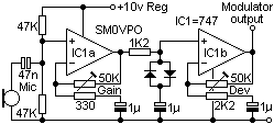
Audio modulator (I used 2 741):
Implementation (I added one mic amp):

The design is by SM0VPO except the mic preamp that is a common preamp circuit

Now for the FM modulation, a super VXO at 10Mhz, bellow:
I used a previous pcb board from the AM light modulator for the buffer power vxo supply (AM for the bitx? Maybe next!). Hard to get parts? probably the BB105 varicap diode but I'm doing some tests with high power zeners (1 and 5W) that probably can be used.

Receiving:
The demodulation part:
The schematic in the receiving part, was an adaptation from a "Russian" schematic I found somewhere, so components values were more or less my interpretation.
The amp before is the same of the one after the crystal filter in the Bitx design..
Honestly schematic looks like a phase demodulator but I still didn't fully understand it, looks more a full wave AM demodulator than an FM one. Fact is, it works to some extend.

The reception part is to be fitted after the crystal filter in the Bitx, of course a new wider filter design have to be used due to FM bandwidth.

The above schematic do works but will need more amplification (another IF amp probably) or at least more impedance match in the reception part, so it's not in for "production level" and I will not put here full schematic. Consider this a starting place for some experimenting.

If you have any simple design for FM demodulation at 10Mhz I would like to know.

Anyhow FM only makes sense for a 10m version of the Bitx or for transverter use.

Have fun!

Tuesday, January 17, 2012

Ciencia an Mirandes - Al Centificu Eilustradu

Or: "Science in Mirandês - The illustrated scientific"

This post is not only about ham radio or electronic design but about an interesting blog I found; not only for the subject in it but because it's written in a language I know very little.... "Mirandês".
This is the first blog I found about ham radio and science in this language, and I found it by mere chance during a web search.

You probably don't know (for the not Portuguese natives, and many natives for that matter) much about this language but Portugal has two official languages (since 1997), yes that's right, beside Portuguese there's also "Mirandês" language.
Mirandês is just spoken by a very small community in the North East part of the country and it's only learn at school in that area, for me and as a simple explanation it's a mix of Portuguese with Spanish adding the country North-East accent. For a language student that could not be the most accurate way of putting things....for English readers to understand I would say it could be a mix of ancient English with current English on a Scotish accent :)

Here's a litle sentence from the blog, in Mirandês and my translation to Portuguese, Spanish and English so you can see similaritires between languages.

In "Mirandês":
"De restu hai uns méźes atras la NASA dixu que punarie outra véç l purgrama an lliña... y ya sta"

In "Portuguese":
"De resto hà uns meses atras a NASA disse que punha outra vez o programa em linha...e já está"

In Spanish:"Además hace unos meses, dijo la NASA volvió a poner el programa en línea ... y ya está"

In English:
"After all, some month's ago, NASA said that would put again the program back on line (track)... and it's done"

I point the fact that language knowledge is an valuable tool, normally my radio searches are in English because of the language wide spread but I do find many interesting pages on other languages like French, Dutch, German, Russian and Japanese, being, from my perspective, the last two the most outside the norm radio designs (specially in component references). So, next time, you, the reader, could try to search something translated to another language, you'll see some different results for sure!

The "ciencia an mirandes" (Science in Mirandês) blog is here

Even if you don't understand the language at least the images and videos are universal.

Have fun, in any language!


Friday, January 13, 2012

Handycam CCD-F370E mini crt - II

I have a spot!


...but before this image, first I cut the vertical deflection coil... had 50% chances of finding it on the first try... I did!


Then cut the horizontal deflection coil (actually I removed the plug on the coils) and got the spot! I new beforehand that the timing/blanking circuit would work erroneous or would stop working since the coil is part of the circuit so I replaced the crt coil in the control circuit with a 33uH or 330uH choke coil (I think... orange, orange, some sort of grey, have to measure and try another), the spot got better and more focused but still not perfect.


..I could just had hook up some signal to the coils...but no! This way is more fun!

Now the problem will be the "Z" axis, I can build an video blanking circuit in tandem with a sawtooth generator (and feed the video in the original circuit) but that would be to much trouble, I will try to control directly the crt or add just a marginal circuit in the blanking part which is pin 11 in the following control circuit.


More search (use an translator if your Russian is like mine...zero, besides: Vodka, Polyakov, Piskunov and Dasvidania! Sorry for the spelling) and I found a similar design (from Samsung) on the one I have:
The red dots are the blanking circuit, I am thinking in "attack" directly "G1" on the tube or maybe the center part of the pot controlling the intensity, (not perfect but should work), I think it's better than removing the tube and make a new HV circuit.

have fun, I am having... a lot!