Thursday, April 15, 2010

The Si570 kit is working!

Thank's to Kees (K5BCQ) help, now the kit is working!

After all it was one of the most common "rf" issues.... power supply coupling. A simple parallel 2.2uF capacitor in the power supply sorted this one out. How can one figure this one out since the problem only happens when addressing memory from 0 to 7.... or going greater than 20Mhz...? Amazing!
Now it's time to put termination on the Si570, boxeit up and make some sort of fantastic radio around this nice litle vfo....


Tested the low end on this particular si570 CMOS and it can go as low as 4Mhz, that is 1Mhz for some types of SDR's. I'm going heterodyne anyhow... bellow 4Mhz will go with an upconverter.

Tuesday, April 13, 2010

Cool boxes for homebrew projects

I placed receivers/transmiters on computer power supply boxes, Sardine an Tuna can boxes, plastic bottles, wooden boxes but never tested on a toaster or lunch box... If the receiver doesn't work or solar activity is low you can always make a nice toast! Found this while "surfing" for relaxing from my homebrew problems (see the end of this article)...


From OH6DC "Toaster tranceiver" at: http://sites.google.com/site/oh6dccw/toastertransceiver

Now for the lunch box (I really like this one..)


Original article at: http://sites.google.com/site/oh6dccw/picnictransceiver

Give a look at the stange cw keys collection (their really strange)... http://sites.google.com/site/oh6dccw/strangecwkeys


This post was supposed to be on the Si570 but after assembly of the kit (see last post) I saw that it is not working 100%. I am "debugging" with the help of Kees (the kit maker) to find the issue with it, everything looks normal but I am having some reset's addressing some memories. I hope I don't have to send the kit for repair, last one it was my fault (very stupid) and I am sure this one is also too! So I want to spare myself the shame... :)

Sunday, April 11, 2010

Si570 kit - new one

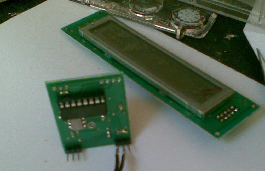
I had this Si570 kit for some time and decided to assemble it...Personally I'm not a big fan of smd devices but had no other choice in this case...

Some stages of the assembly


When I switched it for the first time I had some wrong indication on the display...something like "8.8. 0", tough that something was wrong, checked all the soldering s and...again the same problem.... RTFM and "voilla"... you have to initialize the kit.... after all it was working at first time, remember to read first and solder latter.


This is an excellent kit for a vfo or generall coverage transmitter/receiver (I'm using one in an airband receiver) but the instruction are not the easier to follow so if you want to assemble one I sugest reading the following link:

http://www.cliftonlaboratories.com/si570_kit_from_k5bcq.htm

There's a nice tutorial there... withou it I was proably still reading the schematic righ now...

You can get one kit from here: http://www.qsl.net/k5bcq/Kits/Kits.html

Weather is getting warmer in this side of the world so instead of heading to the shack I might head to the beach.


The outside temperature sensor is bellow the roof tiles...

Wednesday, April 07, 2010

PTO mechanics

The hard part on a making a PTO is the mechanical part so I took some minutes to think about it and started doing one, hopefully it will be somehow stable...
Not much description here, there's an old ball bearing in the shaft and some peaces of aluminum to remove the play. There are 3 nuts to remove (not very successfully) the lateral oscillation/play.


If you have a nice tool shop then please have a look at this one: http://www.qsl.net/g3oou/pto.html

If you are a null working with tools then this one is for you: http://www.wa6otp.com/pto.htm I only wonder what is the sensibility to hand capacity...have to try one...

I would say mine is in bettwen...

still and very important is to place the coil and the moving core....

The moving video, I didn't applied grease yet, ence the noise... just to clear things out...:


This PTO was supposed to be placed in a receiver I am building but the PTO board is bigger so I will use another VFO.
Look at the size of the pre filter if amplifier.... it was a pain to build, the schematic is from BitX (the amplifier I mean), the rest is a mix and is not yet complete.

Saturday, April 03, 2010

Electronics prototype method

Recently I came across a site (http://www.qsl.net/pa2ohh/oldproj.htm) with some ideas on rapid electronics prototyping.


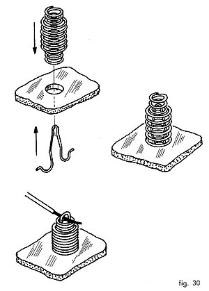
The above mentioned methot is without using solder. When I started on electronics the prototyping boards were very expensive so this was the first method I used, got a little bit of wood, made some holes, bought a coil spring, cute the spring in small elements and placed them on the holes in the wood base. I just didn't used the clamp like this method uses because you just need to bend the spring, put the component lead between the spirals and leave the spring return to it's shape. It's a nice method if you don't have any other way of doing it. The sprimg must be an extension type spring and not a compression type like the above methot uses.

The second method that I allready used, is with small metal thumbtack's placed on a wooden base, you just have to solder the components in them. A photo of one "crystal" radio I made some time ago (the variable capacitor allready went to another project..):


I was thinking if I should bring again the subject on Navtex.... but I will spare you my frustration on this subject. Due to several constraints I normally only have time to make tests on one of the daily navtex transmissions.... that gives me a window of 10 minutes to test the receiver and in some days there's a lot of static and interference so this will take some time until I post a complet working schematic of the receiver. My last experiment was with the divide by "n" circuit (http://speakyssb.blogspot.com/2010/03/divide-by-n.html) connected to an NE602... saw some signals but very burried in noise.
Here the photo of another atempt with the 416Khz vfo wich is not stable enough to leave unatended.


Friday, April 02, 2010

High performance bi-directional mixer / Fooled

Have you been fooled by the last post? No? Ah, you were paying attention to the schematic! Did you order the components? Bad luck... their useful anyhow...
It doesn't work... I think. Just some components placed in paper... It was my April fool! Have a nice day!

Thursday, April 01, 2010

High performance bi-directional mixer

Following some ideas from a fellow ham decided to try an high performance rf front end with easily to find components.
This particular front end is excellent from around 1Mhz to 200Mhz with the added advantage that is bi directional and you can use the same schematic for the BFO part but it's a waist of ferrite cores so use the lower part of the schematic the LM741.


In my preliminary tests this front end had the same performance of my FT-102 and I wasn't using bandpass filters... When the TS-50 was crumbling with BCI this front end was digging out signals from mars... I guess the secret of this design is dividing the signal in two and then combining again out in oposit phase. Will investigate this better tomorow.