..Well, the lights done in last post were a success... not like I would expect but in the sense that I made a child happy.
When I offered the lights the first question was: What's this?.... I immediately tough I made a complete failure, but one second latter I managed to get a quick answer: It's a bicycle speed increaser...and something for other's to see you!... on to put the device on the "veichule" and give some instructions :)
Next day in the morning there goes the kid with the bike on to the city park, after the real "test" he told me it was a complete success! The speed will continue to increase...the more he practices!
Some time ago I offered my nephew an "shooting star catcher".... one magnet removed from an hard drive.... as you know most meteorites are made of iron but what's get's down to earth it's just small sand grains. A magnet will easily pic them up from the "normal" beach sand...not as flashy as a bicycle speed increase r but it's nice to develop kids imagination.
Sunday, December 26, 2010
Monday, December 20, 2010
Season's greetings
Honestly, I try to be the most politically correct in this blog although only at the radio I have the legal obligation for that :)
Said that, and since I don't know the religious or annual (not everybody is in 2010) calendar that each blog reader uses, accept my season's greetings when ever you want!
Here's something to be used as a gift:
Not finished yet (only 3 out of 6 LED's connected and in prototype board) but will be similar to the famous "Knight rider" car lights... what a better use for an 555 and 4017 with at least 15 years old!
This will go to my nephew bicycle. His Christmas present.
Season's greetings!
Thursday, December 09, 2010
Somethings in the "oven"
Nothing special just some updates on an old project and a new transverter.
I am finishing this receiver, just don't know if it's going to be for 40,20 or 17m...righ now it can receive from 160m to 6m with the si570 vfo kit but the idea is to have a simple vfo.
 Still missing is the bandpass filter and the "LSB" oscilator.
A new (for me) 6-10m transverter... right now only the oscillator and the receive converter module without all the coils, but already receiving... the oscilator from the MFJ antenna analyser at 50cm distance :)

Will update ASAP.
I am finishing this receiver, just don't know if it's going to be for 40,20 or 17m...righ now it can receive from 160m to 6m with the si570 vfo kit but the idea is to have a simple vfo.
 Still missing is the bandpass filter and the "LSB" oscilator.
A new (for me) 6-10m transverter... right now only the oscillator and the receive converter module without all the coils, but already receiving... the oscilator from the MFJ antenna analyser at 50cm distance :)
Will update ASAP.
Sunday, December 05, 2010
FT-102 IF output buffer
The Yaesu FT-102 has a lot of outputs/inputs in the back pannel and a lot of controls in the front which is always nice....
Two of the most interesting outputs in the back are the 8.2Mhz and 455Khz IF out marked as 2º and First respectively (strange!?). The 455Khz one is filtered so you don't get many signals outside the pass band but the 8.2Mhz one is just before the 8.2 cristal filter in the FT-102 giving you an overlook on signals after the first mixer. That could be interesting to place an panoramic adapter or a second receiver. I decided to see (level wise) what signals I get there. I you connect directly an HF receiver tuned at 8.215Mhz you will get the same signal that the radio outputs by the speaker (at a much lower level though) also if you go out 10Khz from 8.215Mhz you are listening with 10Khz offset, logic in all similar concept receivers! You get the point, else you were not reading this. The limit is only the passband on the input filters, but they are built to give the entire band.
On to the schematic...
The bufer (from FET pricples and circuits part 2):

The 6K8 on the output was replaced by a 150 Ohm one
The input 220n was replaced by a 100n one.
The buffer output (out) connects to the the amplifier block (bellow) on point 1, point 4 (bellow) connects to the HF receiver tuned at 8215Khz (or the offset you need)
 R is 220 Ohm and C is 100n (tipycal....) transistor is 2n2222, VCC is 12V, remove the 1n4148 diode (replace by a shunt! no need here). This is a block from "bitx" transceiver and works nice.
Those 2 blocks allows to increase the signal level to the point that on a normal HF receiver (TS-50 tested) the signal of the signal meter is more or less the same that the FT-102 is displaying. There are still things to improve like puting a 8.2Mhz "band" wide filter between the 2 blocks or a tuned rf transformer from the radio to the buffer stage.
My idea is to put an panoramic receiver after this buffer/amplifier or connect to a scope for in band signal monitoring.
During tests a single downconverter with an NE602 was conected directly at the amplifier stage output but the NE602 is noisy as hell (or was not well coupled) so will probably replace for something else in the future. Anyhow this was just a proof of concept.
The buffer idea come from here: http://www.carnut.info/panadaptor/panadaptor.htm
Thursday, December 02, 2010
APRS TNC
WB8WGA APRS TNC was a project waiting for the the 16F88 pic programing. Now that it's done I decided to test it using the TH-F7 audio output.
Some frames got decoded but not even 10 %, so it looks like that it has a worst performance than my previous APRS decoder with the 16F628 PIC (http://speakyssb.blogspot.com/search/label/PIC%20based%20packet%20decoder). From what i've seen the audio level must be set very well or else it has some difficulty decoding the frames (same on the 16F628 project).
Other ham's report better success than mine on their's project page, anyhow an absolute test will only be made when the VHF transceiver module is programed with the local APRS frequency.
Here's the external link to the schematic I used.

From here: http://www.kh-gps.de/minitnc.htm
And here fully assembled:

Remember TXD and RXD are reversed if you'r not using the GPS input but an RS232 for computer access to the terminal.
My configuration for the quick receiving test was just:
mycal CT2GQV (that's my call...)
mon all (monitor all the frames)
perm (to save configuration)
* use "help" at the prompt for full command list.
Computer terminal was set for 9600 8N1 no hardware or software flow control.
Some frames got decoded but not even 10 %, so it looks like that it has a worst performance than my previous APRS decoder with the 16F628 PIC (http://speakyssb.blogspot.com/search/label/PIC%20based%20packet%20decoder). From what i've seen the audio level must be set very well or else it has some difficulty decoding the frames (same on the 16F628 project).
Other ham's report better success than mine on their's project page, anyhow an absolute test will only be made when the VHF transceiver module is programed with the local APRS frequency.
Here's the external link to the schematic I used.
From here: http://www.kh-gps.de/minitnc.htm
And here fully assembled:

Remember TXD and RXD are reversed if you'r not using the GPS input but an RS232 for computer access to the terminal.
My configuration for the quick receiving test was just:
mycal CT2GQV (that's my call...)
mon all (monitor all the frames)
perm (to save configuration)
* use "help" at the prompt for full command list.
Computer terminal was set for 9600 8N1 no hardware or software flow control.
Saturday, November 27, 2010
PIC16F88 programing under Linux
I spent all this past week trying to program this 16F88 PIC for the APRS TNC by Bob Ball - WB8WGA. Well, not all the week but a considerable amount of time. Luckily for me I decided to test the programmer circuits in a rapid prototyping board instead of soldering. I think I tested 4 different schematics and 3 diferent software programmers. Here's what worked for me:
Schematic (external link image):
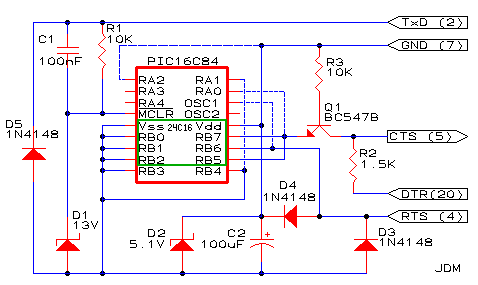 The dash lines are not connected in my prototype and it's a 16F88 pic in place.
Original site is at: http://yingtongdiddleipo.ee.wits.ac.za/help/picprog.html#3
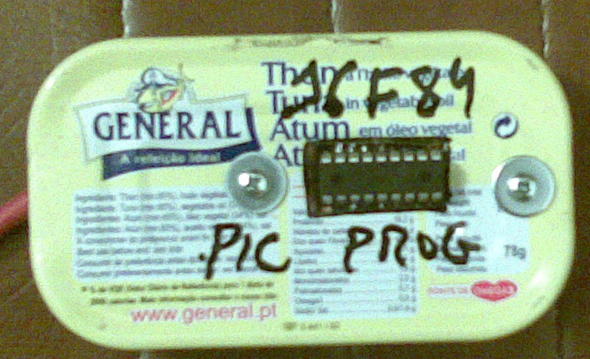
Prototype board with pic in place:

PIC programmer in action:

Piklab version is: 0.15.0
Configuration is: JDM classic (delay 20)
Will probably make a more permanent programmer (in a PCB) but for now it's ok like this, I just needed 1 pic programed.
Now I already have the PIC in place on the APRS TNC PCB and look's that is working good, I have the command prompt and can issue commands! Unfortunately the shack computer is not working well so will test live reception in the near future, probably transmission also.
Schematic (external link image):
The dash lines are not connected in my prototype and it's a 16F88 pic in place.Original site is at: http://yingtongdiddleipo.ee.wits.ac.za/help/picprog.html#3
Prototype board with pic in place:

PIC programmer in action:

Piklab version is: 0.15.0
Configuration is: JDM classic (delay 20)
Will probably make a more permanent programmer (in a PCB) but for now it's ok like this, I just needed 1 pic programed.
Now I already have the PIC in place on the APRS TNC PCB and look's that is working good, I have the command prompt and can issue commands! Unfortunately the shack computer is not working well so will test live reception in the near future, probably transmission also.
What a blast!
After some days without success in some experiments, today was a very productive day.... I just blasted what's left from my DVD reader, I say what's left because he stopped working....I checked the fuse and replaced by a piece of wire (that's plain wrong I know) although having noticed some burned pcb parts I went for it. So I wasn't expecting to much except that 1 second before I though maybe it was a good idea to put the safety googles...before powering up for testing...
Here's the outcome:

The cooper wire over the fuse simply vaporised in front of me... how fun can that be!? :)
Never mind, I just got a new box for some future projects. That's what gives to buy very cheap electronics... they just don't last!
Here's the outcome:

The cooper wire over the fuse simply vaporised in front of me... how fun can that be!? :)
Never mind, I just got a new box for some future projects. That's what gives to buy very cheap electronics... they just don't last!
Tuesday, November 16, 2010
13.8V 20A power supply
...Well it's more like 13.7V and probably 20A power supply since that's the transformer secondary current rating.
I have this project for finish since 2002, it was for some time built but I didn't like the original schematic and now I changed. The original schematic was based on a LM7812 but that creates problems isolating the output transistors (2n3055, what else!). Now it's a more elegant solution based on a 7912 for voltage "control".
here's the schematic:

It is advisable to put an over voltage protection (due to circuit nature and in case any of the "gnd" diodes fail) circuit but for now it's ok for me.
This is a ground regulation circuit so makes it possible to have the collector of the 2n3055 transistors to case avoiding the mica insulators. The output capacitor is critical, without it the 7912 has a tendency to oscillate. The 2n3055 base connected capacitor should be 2.2uF (if tantalum) per amp (on the 7912) or 10 times more if electrolytic, so a 22uF should be enough but the more the better...
Now the working unit under load test (FM mode, high power setting on the TS-50) to a dummy load (didn't measured the input power):
Some more crappy photos:

The ugly "control" board:
 The finished "product":

For now there's no need to put any fan (that's not an optimal dissipator position) because on a normal qso the output transistors don't get enough warm).
Have fun!
I have this project for finish since 2002, it was for some time built but I didn't like the original schematic and now I changed. The original schematic was based on a LM7812 but that creates problems isolating the output transistors (2n3055, what else!). Now it's a more elegant solution based on a 7912 for voltage "control".
here's the schematic:

It is advisable to put an over voltage protection (due to circuit nature and in case any of the "gnd" diodes fail) circuit but for now it's ok for me.
This is a ground regulation circuit so makes it possible to have the collector of the 2n3055 transistors to case avoiding the mica insulators. The output capacitor is critical, without it the 7912 has a tendency to oscillate. The 2n3055 base connected capacitor should be 2.2uF (if tantalum) per amp (on the 7912) or 10 times more if electrolytic, so a 22uF should be enough but the more the better...
Now the working unit under load test (FM mode, high power setting on the TS-50) to a dummy load (didn't measured the input power):
Some more crappy photos:

The ugly "control" board:
 The finished "product":
For now there's no need to put any fan (that's not an optimal dissipator position) because on a normal qso the output transistors don't get enough warm).
Have fun!
Monday, November 08, 2010
VHF FM transmiter using the Si570 (21.4 IF)
Here's the schematic for the new VHF FM transmitter. it's not production grade so please don't try to build this unless you know what you are doing and have an interest in share improvements. With different output filter and amp (none at the moment) I am sure this could be made in to an 10m to 2m FM transmitter, the only limit being the Si570 output frequency capability.

I have to find a 21.4Mhz filter for future testing. Audio is nice but can always be improved. In my prototype both ampop's adjust trim pot are at mid scale.
The core in the coil connecting the NE602 input is a red one (first one if found in the box) and there's no core at the oscillator tuned circuit, just air and near coupling.
Ceramic 10.7Mhz resonator is from one of those cheap AM/FM radios. A crystal would not work nice (to low capacity in the varicaps?) and also tested with negative result with an normal ceramic filter at the earlier prototype stage.
Sunday, November 07, 2010
A lot of issues...
The "pic" on the VHF FM tx just got un-programed.... during tests I cycled the power on butom too fast and that for sure affected something in the internal memories... now it tunes from 148 to 152 and doesn't let me going down or up from this loop....ooh well! I will program the chip again. Anyhow I allready manage to make 3 QSO's with the radio.
Put myself making a simple packet TNC using a pic 16F88 but my simple pic programer refuses to program this model, from what i've searched I am not the only one with this issue... if you have programed the 16F88 with a simple programer please let me know the shcematic...
The simple packet TNC (once programed) will connect a VHF single channel data transceiver module I bought the last ham fair I attened....the programer is as simple as 2 diodes from rs232 txd and rxd to the program pin on the module (connects internaly to RB3 on the PLL PIC)..how dificult can it be?...doesn't work! Trying to sort this one out is driving me crasy! The VHF module is still programed in 156Mhz not exactly what I want...
 The simple DT-102 module programer
 ..I also connect ping 4 on the VHF module side to ground, I think it was missing in the shcematic....see the internal module schematic an let me know if I am not right on this decision.

...pin 4 is ground...anyhow it doesn't work this way or by the programer schematic! Must try in another computer, could be something on the rs232 side....but my another computer doesn't have a floppy drive (to boot the programer software that runs in DOS)... I have a programer software version that runs on Windows...but hell, I will no put that #$%it on any of my computers! :)
On the more or less good side I built a smal VHF FM test transmiter using an 10.7 ceramic ressonator modulated by a varicap to mix the double frequency (21.4) with the Si570 VFO....now, since I don't have a 21.4 filter... I have the 2m frequency output plus or minus 21.4 and 10.7... but at least it works. The mixing is done in an NE602, as soon as I start sorting this issues I will probably use this for transmiter since the Si570 can give the channel step the PLL doesn't.
Here is the test board. The unfiltered and un-amplified test output is just a small piece of wire to pin 5 on the NE602:


I am also looking for a 12.5Khz step PLL replacement for the allready built VHF FM transmiter, this two options look promissing:
http://sq6ade.elektroda.eu/tsa6057.html
http://www.garex.co.uk/AKD/2001_12.5.htm
...Anyhow, no LCD and in both cases a TSA6057 pll chip is needed
Put myself making a simple packet TNC using a pic 16F88 but my simple pic programer refuses to program this model, from what i've searched I am not the only one with this issue... if you have programed the 16F88 with a simple programer please let me know the shcematic...
The simple packet TNC (once programed) will connect a VHF single channel data transceiver module I bought the last ham fair I attened....the programer is as simple as 2 diodes from rs232 txd and rxd to the program pin on the module (connects internaly to RB3 on the PLL PIC)..how dificult can it be?...doesn't work! Trying to sort this one out is driving me crasy! The VHF module is still programed in 156Mhz not exactly what I want...
 The simple DT-102 module programer
 ..I also connect ping 4 on the VHF module side to ground, I think it was missing in the shcematic....see the internal module schematic an let me know if I am not right on this decision.
...pin 4 is ground...anyhow it doesn't work this way or by the programer schematic! Must try in another computer, could be something on the rs232 side....but my another computer doesn't have a floppy drive (to boot the programer software that runs in DOS)... I have a programer software version that runs on Windows...but hell, I will no put that #$%it on any of my computers! :)
On the more or less good side I built a smal VHF FM test transmiter using an 10.7 ceramic ressonator modulated by a varicap to mix the double frequency (21.4) with the Si570 VFO....now, since I don't have a 21.4 filter... I have the 2m frequency output plus or minus 21.4 and 10.7... but at least it works. The mixing is done in an NE602, as soon as I start sorting this issues I will probably use this for transmiter since the Si570 can give the channel step the PLL doesn't.
Here is the test board. The unfiltered and un-amplified test output is just a small piece of wire to pin 5 on the NE602:


I am also looking for a 12.5Khz step PLL replacement for the allready built VHF FM transmiter, this two options look promissing:
http://sq6ade.elektroda.eu/tsa6057.html
http://www.garex.co.uk/AKD/2001_12.5.htm
...Anyhow, no LCD and in both cases a TSA6057 pll chip is needed
Wednesday, November 03, 2010
Bench audio amp
Nothing special here, something I wanted to do for a long time.
When working (testing) with receivers there's no need to build an audio amplifier for each one (test), so why not make an universal one and putting all together in a nice little box...
I didn't draw one of my fantastic s schematics since you can build based on a better one, this one is easier to follow...

Mine doesn't have the capacitor between pin 8 and 1 (gain). The bypass is a 10uF capacitor and the 10 ohm is an 1 ohm resistor. Input dc blocking cap was added.
The final result:
 On the right the input impedance tester and a 50 Ohm dummy load in a round tuna tin. on the left the frequency meter and the dip meter box.
And before being placed in the box:

When working (testing) with receivers there's no need to build an audio amplifier for each one (test), so why not make an universal one and putting all together in a nice little box...
I didn't draw one of my fantastic s schematics since you can build based on a better one, this one is easier to follow...
Mine doesn't have the capacitor between pin 8 and 1 (gain). The bypass is a 10uF capacitor and the 10 ohm is an 1 ohm resistor. Input dc blocking cap was added.
The final result:
 On the right the input impedance tester and a 50 Ohm dummy load in a round tuna tin. on the left the frequency meter and the dip meter box.
And before being placed in the box:

Sunday, October 24, 2010
Made the first QSO...
...With the homebrew VHF FM transceiver! A big thank you to CT1BBP who answered my call and was patient enough to let me test some changes in the radio controls while QSoing!
Audio report was: "looks you are in the bottom of a well but 100% copy!"
That's nice, I am happy, will improve later on the audio modulation part and also the PA with ideas from YO5PBG (he answered my question in a previous post for a PA "ninja" :).

Meanwhile I cleaned up the soldering table and placed some unfinished project's on top for the next few days.
 A 20A power supply (linear), a speaker as a mic and the VHF/UHF receiver with an VCR tuner module.
 Must "clean" this old experiment boards to give space for new projects....
Saturday, October 23, 2010
VHF trx on the shelf
 Here it is....
On top of it, the 88-108Mhz FM receiver and the APT weather satelite receiver. On the right the Si570 VFO and the a TS-50.
Now, there's a little issue with the transmitter... I already knew it but kind of forgot... repeaters have a country wide 12.5Khz spacing but the PLL has 10Khz so I am going to miss some access to repeaters, for now I offseted a litle bit the reference cristal do get the 145.012,5Mhz needed for local access. Since this is not an elegant solution I am now looking for another PLL design probably leaving this one for a separate receiver (it's just a matter of programing the PIC).
Regarding the PA...I allready measured 2W on a 50 Ohm load (specs for the 2n3553 say 2.5W at 175Mhz and 28V, I have 13V and 145Mhz), with my uncalibrated test probe...anyhow it hit's the repeater nicely. I sorted the lack of TO-39 heat dissipator for the PA transistors making my hown model, here's the look of it:

Just roll a peace of thin piece of metal sheet around a 8mm drill and tighten a little to fit the transistor (around 7-8m according to 2n3553 specs).
I first tryed with aluminum kitchen foil but it get's to flimsy:

Monday, October 18, 2010
VHF FM transceiver - live tests
IT WORKS!!!
I have now around700mW output, not the wanted 1W but for now is enough, (I already managed to get 1W but for too much heat dissipation), and I can hit the local repeater with the antenna inside the shack.
If you look at the signal meter, the first level, (1/4 scale), is local signal interference and the second level (around half scale) is the repeater signal before it stops transmiting.
I made some audio loopback tests (recording the audo from the repeater transmission) and it looks good, I mean, it's inteligible :)
Now, the world is not perfect and there's still issues/problems to solve:
1 - Place heat dissipators in the output transistors
2 -Sort the problem in the PLL subsystem, sometimes there's no display indication and or garbage and PLL will not lock. Look's like it was a bad solder joint.
3 - There's some delay (half second or less) between hitting the ptt and getting audio via the repeater. Will have to see if it's a delay in the output stage power on and/or PLL unlocking or some delay at the repeater level.
4 - Check modulationlevel deviation and harmonic generation... will have to study a little bit more on how to verify this!
5 - Make a live QSO.
6 -Finish the project box. Assemble the project box
7 - Put in the shelf....
And now, so that you don't to the same mistakes I did:
1 - Check if your transmit monitor radio is in FM and not SSB mode while doing transmiter tests....
2 - Check if you realy are in the correct repeater tone. I was on the wrong tone and took me a lot of time to undesrtand why the repeater wasn't activated.
3 - Just because when you hit the PTT you listen to some sound on your monitor radio that doesn't mean it's your signal coming from the repeatar. If the monitor radio is close enough you probably are geting a lot of signal localy!
4 - Watch out for loop current's.... in doubt remove the ground connection on any point to point cable.
Stay tuned, for more fun!
Addendum: I can hit the local repeater with the dummy load connected...it's leaking somewhere....
I have now around
If you look at the signal meter, the first level, (1/4 scale), is local signal interference and the second level (around half scale) is the repeater signal before it stops transmiting.
I made some audio loopback tests (recording the audo from the repeater transmission) and it looks good, I mean, it's inteligible :)
Now, the world is not perfect and there's still issues/problems to solve:
1 - Place heat dissipators in the output transistors
2 -
3 - There's some delay (half second or less) between hitting the ptt and getting audio via the repeater. Will have to see if it's a delay in the output stage power on and/or PLL unlocking or some delay at the repeater level.
4 - Check modulation
5 - Make a live QSO.
6 -
7 - Put in the shelf....
And now, so that you don't to the same mistakes I did:
1 - Check if your transmit monitor radio is in FM and not SSB mode while doing transmiter tests....
2 - Check if you realy are in the correct repeater tone. I was on the wrong tone and took me a lot of time to undesrtand why the repeater wasn't activated.
3 - Just because when you hit the PTT you listen to some sound on your monitor radio that doesn't mean it's your signal coming from the repeatar. If the monitor radio is close enough you probably are geting a lot of signal localy!
4 - Watch out for loop current's.... in doubt remove the ground connection on any point to point cable.
Stay tuned, for more fun!
Addendum: I can hit the local repeater with the dummy load connected...it's leaking somewhere....
Friday, October 15, 2010
Box for the PIC programer
 I had the pic programmer (for 16F84 and similar type) for some time on top of the computer box, built it in a rapid prototype board, so decided to give him new shiny box so I can place it in the "not so frequently used equipment shelf".
Now, why to spent around 10 Eur in an aluminum box when you have some other for around 1 Eur, that's ten time's less...and you can eat some tuna or sardine fish! Yes, I am writing about the mighty tuna tin!
Here's the outcome:
 Inside:
PCB come from the VHF PLL board left over, and, by the way, the "tuna" was very nice!
Schematic at: http://speakyssb.blogspot.com/search/label/PIC%20programmer%20for%20APRS%20tracker
Meanwhile, made some more tests in the VHF 1W amplifier and now I only need more 1.2V to get the 1W mark! Maybe next few days...
Wednesday, October 13, 2010
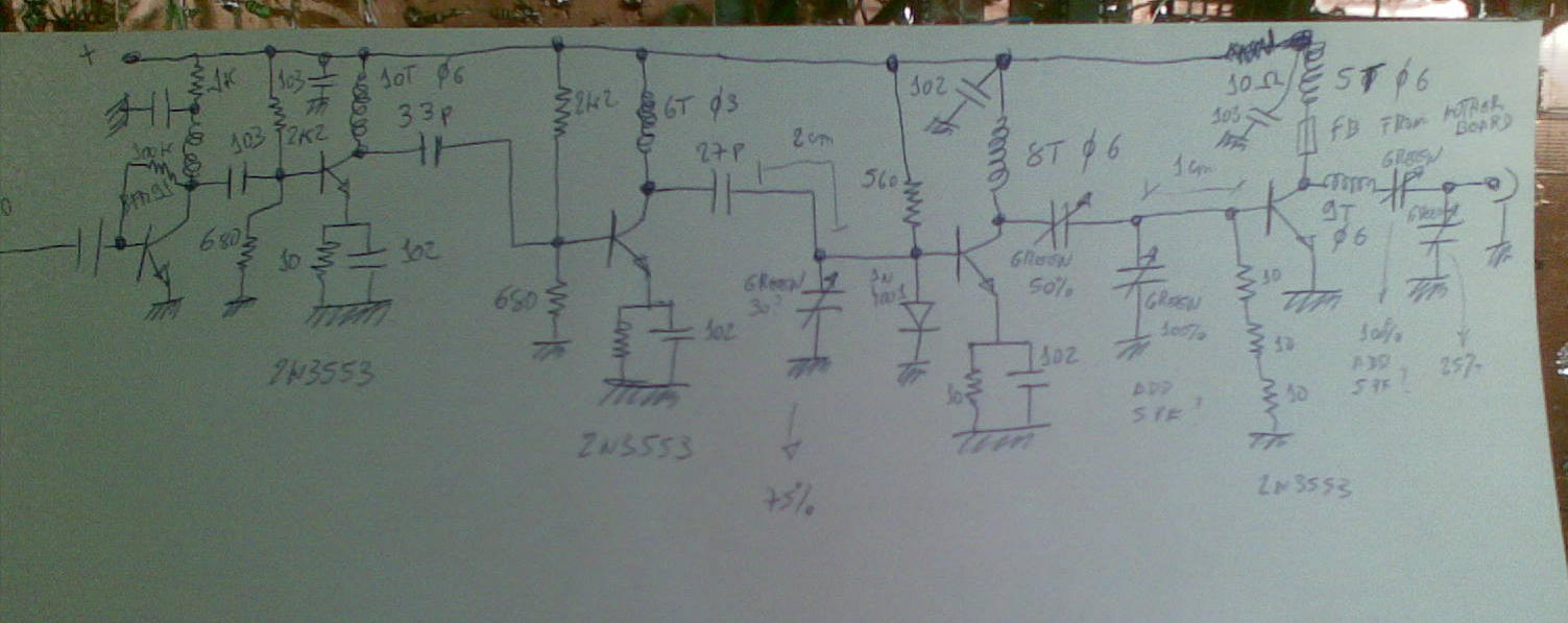
VHF amp...first schematic

After 3 burned 2n3553 I am starting to get the "touch" on building VHF amps... or not...
Well, after some problems, at some point in my tests, I manage to get more than 1w out....but just for a glorious 1s before another blown 2n3553 ruin my day, guess they can't withstand the drive I was putting. Why did I not keep this "successful" schematic? Probably with some small changes it would work nice but I started changing things and then never again got that output value.
Never giving up and after some more hard testing, yes because, every time you change some biasing you have to tune all the stages again, I now get 0.5W output.
Total current on the 4 transistors
 That's roughly 13W dissipation... to much for 0.5W output. It's good to have a current meter when testing...if you get more than 1.3A, for a few seconds, in a 2n3553 you must expect that he would die... never the less I have been seeing them withstand some 0.5-0.8A for short bursts. Just don't touch them after... I have more finger burns than transistor...
Voltage at the 50 Ohm load (5.01V is 501mW, 7.07V is 1W)
 I am less than 2V away from total success!
This amp has 4 stages after the buffer and all of them use 2n3553 transistors (my choice).
There's a lot of dissipation on all stages except the last one that works in class C so there is for sure a lot of improvement to do. My main issue is getting the right level to drive last stage without warming to much the transistors before.
The following schematic is here just as a placeholder and needs a lot of improvement but I need a base to work and record the changes made.
I am open to suggestions for removing one transistor from the schematic and specialy for transistor biasing and inter stage coupling...
 If some VHF amplifier "ninja" reads this, please get in touch... I like to learn!
Friday, October 08, 2010
VHF amp...and the transmiter schematic
I am now in the process of building another version of the 1W VHF amplifier for the FM transceiver, well, in fact, it's still the same version since I didn't managed to get 1W... YET!
Today I made some tests with a 2n2553 and a 2n2866.... it melted solder in one of the base resistors (never I had seen such a thing, normaly resistors burn), a 27 Ohm one, made with 3 different resistor.... but the power was: 1.6mW thats mili! So I still have to learn a little more on VHF amplification... 2 more 2n3553 went belly up...it's always the emiter junction that breaks :)
Anyhow, Pedro - CT5JZX, today sent me a schematic he found for me to have a look and get some ideas! Funny, it's basically the same schematic I use on the transmitting part, that's normal, most parts of my schematic came from Miguel - PY2OHH site.
Here's the said schematic linked from PY2OHH site:

My schematic is only different in the following parts:
Tone encoder: I have a diferent design, but the connection place is the same, also I use the same IC.
VHF oscilator buffer (BFR91 with 100k to base): I have two, one for the PLL and the other for the output amp part. Both connect to the same place via DC decoupling caps.
Oscilator: I don't use the trimer for frequency adjust, I placed a fixed cap after some tests.
Mic amplifier: I don't use an electro mic, so don't need the polarization circuit.
PLL: The same
I am trying to make the final output with 3 2n3553 or 2 and one 2n3866 transistors but if no success I migh just copy Miguel design!
Anyhow, if you need an VHF FM transmiter, this is a design to follow, tested by two...at least!
Today I made some tests with a 2n2553 and a 2n2866.... it melted solder in one of the base resistors (never I had seen such a thing, normaly resistors burn), a 27 Ohm one, made with 3 different resistor.... but the power was: 1.6mW thats mili! So I still have to learn a little more on VHF amplification... 2 more 2n3553 went belly up...it's always the emiter junction that breaks :)
Anyhow, Pedro - CT5JZX, today sent me a schematic he found for me to have a look and get some ideas! Funny, it's basically the same schematic I use on the transmitting part, that's normal, most parts of my schematic came from Miguel - PY2OHH site.
Here's the said schematic linked from PY2OHH site:
My schematic is only different in the following parts:
Tone encoder: I have a diferent design, but the connection place is the same, also I use the same IC.
VHF oscilator buffer (BFR91 with 100k to base): I have two, one for the PLL and the other for the output amp part. Both connect to the same place via DC decoupling caps.
Oscilator: I don't use the trimer for frequency adjust, I placed a fixed cap after some tests.
Mic amplifier: I don't use an electro mic, so don't need the polarization circuit.
PLL: The same
I am trying to make the final output with 3 2n3553 or 2 and one 2n3866 transistors but if no success I migh just copy Miguel design!
Anyhow, if you need an VHF FM transmiter, this is a design to follow, tested by two...at least!
Wednesday, October 06, 2010
VHF FM transmiter... On air tests
YES! It works! In fact this is my first second transceiver ever built (the Pixie was the first)! The others or aren't finished or are separated units!
The crappy photo and the lousy video:

There's no image in the video since it's difficult to hold the camera while talking to the mic some 2m away! The sound comes from the TM-D700 with the antenna about 3m away from the vfo buffer and output amplifier disconnected.
Now, there's still some improvement to do on the tone encoder, the final amp and connect the rx/tx circuit. The tx vfo is some 40Khz offside from display frequency but I think that's because the PLL crystal is not trimmed to frequency yet.
Tuesday, October 05, 2010
Updates on the VHF transceiver I
The VHF FM receiver part is done! I made some more tests trying to put the APRS packet decoder working with this receiver but no success. Will leave only the discriminator out and them with more time in the future will see what's the problem. Never the less, with the computer sound card I can decode nicely the APRS packets.
Here's how it looks line now:
 The top PCB is the transmitter one that will occupy me for the next times.
I found a 4.5 Mhz cristal in an old car radio that will fit nicely in the PLL transmiter board...what a luck since the part was getting dificult to find and I was making tests with an ceramic filter doubling as oscillator.
Now some other things...
I still think in making a simple, standalone NAVTEX receiver. After some sucessfull experiments my only problem is to get a cristal combination (for filter and LO) that allows reception of 490 and 518Khz transmissions, I want to avoid PLL, DDS or any other more complex method for the LO frequency. In the past I made some experiments dividing frequency but doesn't hurt to try some more like the ones bellow (external site image):


PA1GSJ blog has also some topics on this subject of finding crystal combinations, and also subharmonic mixers (easier than making a frequency divider). You can read more at: http://draaggolf.blogspot.com/
If you have any idea on a crystal combination that migh work on 490 and 518Khz I would like to ear... preferebly those frequencies plus 1.5Khz to avoid inverting mark and space. Thank you.
Here's how it looks line now:
 The top PCB is the transmitter one that will occupy me for the next times.
I found a 4.5 Mhz cristal in an old car radio that will fit nicely in the PLL transmiter board...what a luck since the part was getting dificult to find and I was making tests with an ceramic filter doubling as oscillator.
Now some other things...
I still think in making a simple, standalone NAVTEX receiver. After some sucessfull experiments my only problem is to get a cristal combination (for filter and LO) that allows reception of 490 and 518Khz transmissions, I want to avoid PLL, DDS or any other more complex method for the LO frequency. In the past I made some experiments dividing frequency but doesn't hurt to try some more like the ones bellow (external site image):
PA1GSJ blog has also some topics on this subject of finding crystal combinations, and also subharmonic mixers (easier than making a frequency divider). You can read more at: http://draaggolf.blogspot.com/
If you have any idea on a crystal combination that migh work on 490 and 518Khz I would like to ear... preferebly those frequencies plus 1.5Khz to avoid inverting mark and space. Thank you.
Thursday, September 30, 2010
Discriminator out of MC3361

Now that the VHF FM receiver part is almost done, nothing like giving it a little "professional" touch...said that, on to make a "packet" dedicated output, also know as discriminator out...
Basically this output is a low pass filter from the recovered audio of the MC3361. The same signal goes to the speaker amplifier, so it's just a matter of filtering and preserving the signal in it's more pure form.
I add an amplifier because the sound card wasn't liking the very low output of the MC3361. The "filter" part is just the 5k6 resistor and the 4.7nF capacitor.

Before making the amplifier I tested for some time with the my PIC aprs decoder but not even one packet was decoded (it's working/well connected since I get the boot message and the blinking led...)
Then I proceeded to "multimon" software, now with the amplifier working, had limited success, about 20% of all packets were decoded (remember, I am using a peace of wire as antenna inside the shack). By this time the TM-D700 was decoding around 95% (I was beaten by a kitchen electronics manufacture).
Bellow, "multimom" decoding:

Also tested with "soundmodem" software but no success. I didn't proceeded with further testing since I installed and tested "multimon" and "soundmodem" today for the first time. Could be my mistake in the configurations.
Hope to get better results in the future with the outside antenna.
I also tweaked the IF frequency a little bit and the quad coil to try improving reception but not much success.
Incidentally I found a PIC aprs decoder project with an LCD that migh work a litle bit better since is based on the MX614 chip, unfortunately is very hard to find the MX614, so for now I will put on standby this project. Here's one of the links:
http://www.ke4nyv.com/peekpack.htm
Further reading:
* http://www.xastir.org/wiki/HowTo:SoundModem
not in documentation but port on "Xastir" should be configured at 4800 and probably you need to "chmod" a+rw /dev/pts/"whateveryours"
* http://www.baycom.org/~tom/ham/linux/multimon.html
Download link for "multimon" is at the bottom!
* http://www.discriminator.nl/
Sunday, September 26, 2010
Akihabara
Normally this blog is just about building or experimenting but I will open an exception that got me depressed.... a lot depressed...you know, when you want someting and realise that it will take for ever to get...or never!
"Akihabara" is from what I know an area in Tokyo devoted to the electronics market.
I've seen, in the past, some comments and some photos about it but never had seen a more inside look.
Please visit http://www.tokyohackerspace.org/akihabara/
and browse from the shops on the right of the video. If that doesn't get you depressed then you must live there. This is something like Friedrichshafen times 1000 and on steroids.
Isn't the world unfair?.... sometimes even a 1N5711 diode is difficult to find locally and this guys have all the components in a metro station!
I am still depressed..... cheapest fligh to Tokyo is allmost 3000 Eur :)
Friday, September 24, 2010
From junk to a power supply
I've been given an old VCR....I hope it was not working since it was immediately opened for parts.
One of the nice things is; this one had a linear power supply with a real transformer and not that interference causing switching thing's :)
Said that, time to remove the transformer. I didn't care for reverse engineering the power supply diagram, just cut'd the transformer away and the rectifier bridge dissipator wich had also a 7812. I didn't reused the filtering capacitors since I had a new one to put giving a little more confidance.
And here's my new bench power supply, half done. There are still holes for other voltage outputs. For now only 15 on the left side and 12V on the right.
 You can see in the background the VHF RX/TX being built and far away the RF power meter
The internal mess:
 Need to put a fuse outside, for now it is internal on top of the transformer (also reused).
If you need the schematic....go search the net :) There are a billion power supply schematic's around...
And here's the trusty old bench power supply!

Is this junk with style or what? :)
Wednesday, September 22, 2010
Georg Simon Ohm law
Now, after all this years, this is the first time I know Ohm's first name (never met him dough), some other authors/researchers/inventors I learned the full name at school but I don't recall any teacher referring to Georg Ohm... we are always learning.
Why a topic on Ohm's law, well, just because I needed some relax from more complicated maters (for instance an inverter gate oscillator that is refusing to start with a recycled 4.5Mhz ceramic filter. It starts with a transistor oscillator configuration!).
Now let's do a simple demonstration about Ohm's law:
Place a 9 Volt power supply feeding a 2.2K Ohm resistor in series with a red led (the led is just to brighten things a little bit)
Now measure the voltage across the resistor. In my case I measured the total voltage applyed

then removed the led voltage.

To get: 8.82 - 1.90 = 6.92 Volt across the resistor, measured directly should give the same result.
So, let's calculate the current passing trough the resistor (and the led because it is in series) by Ohm's law:
I = U / R
That's: current is equal to the voltage divided by the resistance.
Since the resistor is a 2200 Ohm one...
I = 6.92 / 2200
I = 0.00314 Ampere
I = 3.14 mili Ampere
let's then measure the current to confirm our calculation:

Now that's a 60 uA (micro Ampere) difference... maybe Mr. Ohm was wrong although 60 uA in 3140 uA is a very, very, very small difference.
But what would happen if my resistor was a 2150 Ohm, as I measured.
 Then the current would be 6.92/2150 = 3.21mA that's rounded to 3.2mA and yes...we can confirm that Mr. Georg Simon Ohm was correct!
The very small difference is due to the precision on the multimeter. That's another subject just by it self...
Thank you Mr. Georg for all the fun!
Incidentally I came to the conclusion that I don't know any LED reference value....normally one just ask a 5mm red led...or green. Who cares!?
Subscribe to:
Posts (Atom)