
After 3 burned 2n3553 I am starting to get the "touch" on building VHF amps... or not...
Well, after some problems, at some point in my tests, I manage to get more than 1w out....but just for a glorious 1s before another blown 2n3553 ruin my day, guess they can't withstand the drive I was putting. Why did I not keep this "successful" schematic? Probably with some small changes it would work nice but I started changing things and then never again got that output value.
Never giving up and after some more hard testing, yes because, every time you change some biasing you have to tune all the stages again, I now get 0.5W output.
Total current on the 4 transistors
 That's roughly 13W dissipation... to much for 0.5W output. It's good to have a current meter when testing...if you get more than 1.3A, for a few seconds, in a 2n3553 you must expect that he would die... never the less I have been seeing them withstand some 0.5-0.8A for short bursts. Just don't touch them after... I have more finger burns than transistor...
Voltage at the 50 Ohm load (5.01V is 501mW, 7.07V is 1W)
 I am less than 2V away from total success!
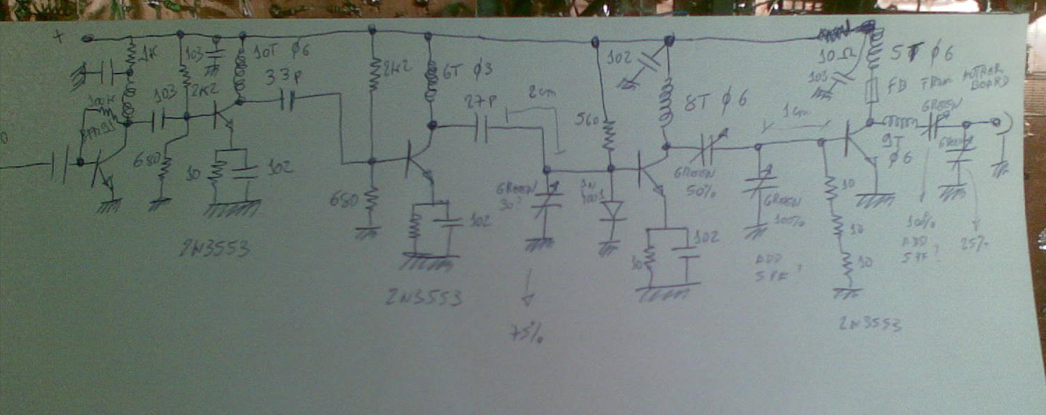
This amp has 4 stages after the buffer and all of them use 2n3553 transistors (my choice).
There's a lot of dissipation on all stages except the last one that works in class C so there is for sure a lot of improvement to do. My main issue is getting the right level to drive last stage without warming to much the transistors before.
The following schematic is here just as a placeholder and needs a lot of improvement but I need a base to work and record the changes made.
I am open to suggestions for removing one transistor from the schematic and specialy for transistor biasing and inter stage coupling...
 If some VHF amplifier "ninja" reads this, please get in touch... I like to learn!
4 comments:
A 5 stage amplifier for 144Mc should be able to output more than 30W! with a very little input signal from a diode mixer...
The 1n4001 diode is not well placed. Use a RFC in series and a capacitor to GND in parallel with the diode...
Most of problems are from bad matching (impedance) between stages.
You should obtain 1W with only 3 transistors: only the last must be 2n3553, don't have to use it in low power stages.
For better result use as first ampplifier a mosfet, with bifilar transformer in Drain an 1nF coupling capacitor ti the base of next stage... from the median of the transformer. Input impedance of FET is HIGH!
With only a MOSFET and 2N3553 you must obtain between 100mW and 1W ... depending on your iput level.
Don't forget good matching at collector of 2n3553.
Good Luck.
BTW, 5V on 50 ohm is 0.25W :)) not 0.5W as I know. Formula for output power is P=U*U / 2xZ
2xZ = 100 (at 50 ohm)...
Also use analog meter for verifing voltage, after detection. Low cost Digital meters can give eroneus readings.
73
Adrian,
Thank you for your post comment.
I will read more carefully your valuable opinion and re-design the amplifier, I am aware his limitations (hence mine's) but it kind of worked although not perfect :)
Choice on 2n3553 is that their cheaper than 2n3866 and similar and can withstand a lot of abuse from an inexperienced amateur!
Regarding the power I think I am correct: P=R*I*I and I=U/R so I=5/50=0.1 so P=50*0.1*0.1=0.5W
73 de Ricardo - CT2GQV
Ricardo, that is the "almost " the corect formula :-). But in RF if yoyu rectify the voltage with a diode in series with 50 ohm load plus the capacitor from diode to ground, you should use the formula that I gave you because you measure peak voltage not RMS.
See for example the formulas described here: http://www.aa5tb.com/qrpmeter.html
GL.. if problems, give me an e-mail describing your station to know what schematic to give you.. for amp.
Post a Comment