Friday, January 29, 2010
New colors for 2010
No soldering today so I had to do something... nothing like using the full features of "css" and give a new look to the blog... hope you like... if you don't like go for another site... there are more than 2 in the internet :) You can chose.
HF radio... some tests
...almost there, at least the receiving part. Just finished the variable center frequency audio filter now the only thing missing is the AGC circuit due to redesign. Manual AGC is working. I still need to make the rf pre-amp and attenuator but they will not populate the main board. Next few days will try to start the transmiting part.
Variable center frequency audio filter at: http://py2rlm.sites.uol.com.br/filtroegl.HTM

In the video the first control used is the variable audio filter (shcematic above) then the switch to put "on" the audio notch filter and then USB/LSB selector. The filter are not perfect because not much care was made to ensure equal components on both opamp's.
Variable center frequency audio filter at: http://py2rlm.sites.uol.com.br/filtroegl.HTM
In the video the first control used is the variable audio filter (shcematic above) then the switch to put "on" the audio notch filter and then USB/LSB selector. The filter are not perfect because not much care was made to ensure equal components on both opamp's.
Saturday, January 23, 2010
And.... the NE602

If they didn't cost'd me around 3 Eur each I had slammed the hammer over them....
The NE602 is giving me a little of a trouble, I change the hf-radio product detector from the SBL-1 to an NE602 based. Problem is I started using the same schematic on the K2 but without the cristal filter betwen the MC1350 and the NE602, tryed the Minipig 10 and also the Malta 40 schematic (both qrp radios) but it's not easy to interface the NE602 at least to get maximum performance. Best result so far was an output transformer on the MC1350 with midle power supply coupled to another transformer on the input of the NE602.

Unless I get better result soon will revert back to the SBL-1, the price is not that diferent. I have to say on the schematic of the Malta 40 qrp I didn't used a Toko coil but made the IF transformer with an FT37-43 toroid. The main problem is with some combination of values I have a big wistle sound on the output, I gess is overdriving the NE602. In the future will try to replace the MC1350 also, it's noisy has hell... but it's simple to make and I never designed anything better :-)
Anyhow changed also the bias on the first preamp after the first mixer.
Schematics involved:
Minipig 10
http://www.kitsandparts.com/minipig/mp10.gif
Elecraft K2
http://www.elecraft.com/manual/ELECRAFT%20K2%20Owner%27s%20Manual%20Rev%20G%20WEB.pdf
Malta 40
http://www.karinya.net/g3txq/malta40/malta40.pdf
Thursday, January 14, 2010
Port-au-Prince
The first time I heard this name was some 5 years ago, planing a small trip to the
Caribeean french Martinique island, whille searching for airports in the Caribe area I spoted this name and when I went to to buy the plane ticket I incidentally asked for Port-au-Prince, when I wanted to say was Fort de France, the lady looked at me shocked and I quickly spoted the mistake and asked Martinique, Fort de France. I went to Martinique.
Now the news bring me again this rememberance... has you know that part of the island was hit by a very big heartquake and caos is installed.
There were allready some ham radio contacts to the afected area has you can listen here: http://d.yimg.com/kq/groups/12397727/1885578730/name/Haiti%2Emp3
News at REP: http://rep.pt/geeklog/article.php?story=20100114010620591
Looks like HH2JR managed to put his station on the air.
HH2JR used a phonepatch from a fellow ham in the states to relay some news on the situation. This reminds me I have no phone patch in the shack and probably is a good idea to brew one.
I allready have a batery charged from a sollar panel in case there's a power outage.
Thinking in what I can do to help out and since I have not much economical power, instead of my next journey to the electronic shop to buy some relays I need for the hf-radio, I will use that money to send to the Portuguese red-cross relief effort since they are now sending people to the affected area. The hf-radio can wait a little longer on the relays.
If you, the reader, can help them out in any way, please do!
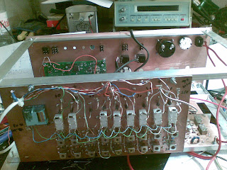
That missing relay will have to wait, like the antenna changover, attenuator and rf preamp:
Caribeean french Martinique island, whille searching for airports in the Caribe area I spoted this name and when I went to to buy the plane ticket I incidentally asked for Port-au-Prince, when I wanted to say was Fort de France, the lady looked at me shocked and I quickly spoted the mistake and asked Martinique, Fort de France. I went to Martinique.
Now the news bring me again this rememberance... has you know that part of the island was hit by a very big heartquake and caos is installed.
There were allready some ham radio contacts to the afected area has you can listen here: http://d.yimg.com/kq/groups/12397727/1885578730/name/Haiti%2Emp3
News at REP: http://rep.pt/geeklog/article.php?story=20100114010620591
Looks like HH2JR managed to put his station on the air.
HH2JR used a phonepatch from a fellow ham in the states to relay some news on the situation. This reminds me I have no phone patch in the shack and probably is a good idea to brew one.
I allready have a batery charged from a sollar panel in case there's a power outage.
Thinking in what I can do to help out and since I have not much economical power, instead of my next journey to the electronic shop to buy some relays I need for the hf-radio, I will use that money to send to the Portuguese red-cross relief effort since they are now sending people to the affected area. The hf-radio can wait a little longer on the relays.
If you, the reader, can help them out in any way, please do!
That missing relay will have to wait, like the antenna changover, attenuator and rf preamp:

Wednesday, January 13, 2010
HF Bandpass filter for the hf-radio

.....Reminde me to buy a ready made bandpass filter next time.... or to make a classic pcb....
I am in the process of soldering the bandpass filter for the hf radio but it's taking some time since there are a lot of connections and a lot of glue to put up, times 9 bands...
Maybe I can finish it today...
.... done... only the connection from each filter output to the relay is not done. 160m band has no control at the moment... for some strange reason ethernet cables only have 8 conductors ;-)

Design is from the GQRP club and the control circuit is my design. Honestly a simple transistor (bc547) as a relay switch.
Tuesday, January 12, 2010
For the new year
...I hope to make at least 1 qso, preferably with my homebrew hf radio, since last year of 2009 none was made. Well I do prefer to solder than to make electromagnetic noise...
Here is the QSL card I use to send.... well I confess... there are some in the backlog... sory for those who have not received yet the QSL card, it`s not forgot.


Have been busy with other stuff but I am already making the bandpass filter for the hf radio. Will post schematic and photos asap.
Have a nice 2010!
Tuesday, January 05, 2010
S9 signal generator

....I just knew it was to easy (on the online pdf) to be true....
When you finish soldering and go for a test then it's when the s!"#!" hits the fan...
I was looking for a test generator to start testing MDS on my new hf-radio (somewere on this blog). I could just get my cristal tester and place some attenuators, but no, I had to look for a specific schematic.... guess what, Elecraft make's a nice little kit, the XG2, (http://www.elecraft.com/manual/E740084%20XG2%20Manual%20Rev%20E.pdf).... I am sure them works... not my homebrew copy... I didn't had the reference regulator in the schematic so I replaced for a 1.5 Volt's battery removing the left part of the schematic (the 3v battery). I had heard that is not easy to make low voltage oscillators, mine didn't worked has in the original Elecraft schematic so I made some small changes. It could had been the type of crystals or any other thing but in fact I could just make the circuit start oscillating at around 2.8V
My schematic:

Anyhow the main output gives around S9+5 on my Yaesu FT-102 and around the same on the Kenwood TS-50.
I have some leakge from the attenuator so on 1uV setting I have around S5. Am now in the process off making a 34db (will probably make a 40db) attenuator with some blindage to try to get the S1 level. Will try an online attenuator tool: http://www.g4nsj.co.uk/attenuators.shtml
I didn't had the crystal frequencies specified on the schematic so I used for now 10Mhz and 4Mhz. At least with the 10Mhz I can test on the Yaesu, Kenwood and my new radio for comparation.
The box was from a previous PSK/RTTY interface, and no it's not a wine or wisky box, it's from a perfume. Cheap and easy.
addendum:
Added a 40db attenuator (2 times 51 ohm and 2.5Kohm PI)and now have more or less S0 (can't measure level). Can't listen to it on the FT-102 without preamp (to FT-102 favor, there is a birdie at 10Mhz that overlaps). Can listen to this low level on the TS-50 (IPO in and out). On my homebrew radio.....well.....I can listen! Very, very faint but I have no preamp at the moment!
Subscribe to:
Posts (Atom)