Tuesday, December 30, 2014

Anatomy of the Sailor R104 receiver

From the previous post you know I bought an Sailor branded R104 and a T126 companion transmitter in possible working state...

I had now the chance to test the receiving section, the R104.

It works....at least the channelized part of the receiver, the bands parts it's not working, will have to investigate it. The bands and the channelized part don't share the mixer and part of the front-end so most likely issue is there.

I have to admit that the radio is not exactly built like a tank (internally, as in some military equipment) but is very well thought in some build details, I think the builders main concern was the entrance of salt water in the equipment so although not waterproof it has some rubber parts to seal the most exposed parts and also some oil embedded cotton in the potentiometers shafts. Also the outside enclosure almost bullet prof.

Here some photos:

Speaker "cabinet":

The speaker itself:


The oil embedded cotton seal and front panel rubber seal:

The speaker output plug was broken and some previous owner tried to fix with scotch tape, very bad work, I already bought a matching one to replace and keep the radio the most original possible way (was the last similar phone plug in the shop):


Another previous atempt on fixing the radio, there are ruber seals around the regulator and plugs panel and they were glued to the back pannel only a poor job was done and the ruber seals ended sliping from the orignal possition:


Internally, pre-selector and channelized part:

 Difference oscillator 7.3 - 6.7 Mhz (two crystals on top board) for clarifier, the other boards I think are the IF amp and AGC circuits

USB filter and  bands oscilator


Well... it will be my restoration project every time I return to Portugal for some vacations.

I wish you a happy 2015....and 2016... and so forth!


Tuesday, December 09, 2014

Sailor R104 + T126

I know, did I needed this boat anchor?  Probably not!

Sorry, couldn't resist since this was the only radio I managed to break in operation (many years ago and that's another story)... luckily was only the fuses and that because the antenna cable was corroded...

There's nothing like the first love, so I bough this exemplar relative cheap and in supposed working condition (didn't tested yet). The radio was delivered in Portugal last week and I had no time to power it up, maybe during Christmas week.

It's composed of two main modules, the transmiter T126 and the receiver R104, aditional modules are the power supply, the speaker and the external antenna relay. Only the mic is missing.
 Weight is around 26 Kg, now that's a proper anchor!
There's a metal support that you can use to fix it to a wall and allow the modules to slide in for easy maintenance.

Transmitting part and power supply:
 

Receiver and speaker:


Inside the transmitter:


And the corresponding schematic:
.... that is 6 output TT22 valves for something around 400 W...

Modulation part of the transmitter:

I might in the end just use the transmitter unit for parts, specially the output tubes and the crystal filter.

Schematic and ssb filter characteristics (modulator):

Note the asymmetrical characteristic of the filter:


 ...you probably noticed my blog pictures quality just passed from the normal "crap" to something more acceptable, that's because I have a new camera, unfortunately you have to keep the same photographer...

Have a nice week!


Monday, December 01, 2014

Silicon Labs Si5351A loaded output

I'm really considering this device (Si5351A) to be the VFO and BFO for my new transceiver (Trevo).


I implemented some code, on the Arduino, to change frequency depending on the position of a potentiometer since I'm waiting some rotary encoders to arrive.

While I don't proceed with more code, started to investigate the best way to interface the output to an ADE-1 mixer since I'm using them on the "Trevo".
 Saying that: connected the oscilloscope probe to one of the Si5353 outputs and started measuring:

Unload (or for that mather loaded with the scope probe) I got around +19dbm.... _if_ the voltage was applied on a 50 Ohm load (measured 2 V on the scope).... that looks promising...., let's try loaded... and it drops to the following values and matching load (a carbon resistor was used):

47 Ohm: 316 mV
100 Ohm: 700 mV
220 Ohm: 1V

That sayd then the output impedance is 220 Ohm, not even a calculator is needed...

The stated datasheet impedance, for the Si5351, is 85 Ohm, I might be doing something wrong or not taking in account something else... I might try again with the probe in 10x to raise the scope loaded impedance.

 Anyhow loaded with around 50 Ohm (47) that's still +3 dBm, enough for some more testing ...
 Test frequency was 19.100 Mhz,


Have a nice week!

Sunday, November 23, 2014

Scope bandscope adapter in place

I'm getting to the point that before building something I allready know were it can fail and if it will work....
So confident with that, I build this small banscope adapter for the Yaesu FT-102 without even testing it on the radio itself and in the scope was intended to (Hameg). That was because I don't have the radio in Ireland.
So I took the finished equipment to Portugal (were the FT-102 is) and connected to the IF2 out..it worked first time!


Still have to finish the front panel labeling and build a small buffer in the output of the FT-102, there is some leakage to it. Also if you notice I connected incorrectly the power button and LED....oh well. There's some initial drift of the bandscope VFO oscillator, maybe in the future will improve the VFO design.

Here during build and tests using just a small carrier to test and the Rigol scope (you can see trigger channel signals also):


The bandscope internal board during build:


If I have time will draw the schematic but basically is a receiver with a ramp generator sweeping the VFO, the output of the IF filter (in that receiver) is connected to an AD8307 and the AD8307 output to an oscilloscope Y, scope X is triggered by the ramp or by the pulse output of the bandscope sweep generator (I choose pulse on my case).


Have a great week!

Sunday, November 02, 2014

Park Air Electronics VHF receiver external PLL control

When I bough the Park Air Electronics VHF receiver Model 2100, last year, the idea was if it was not worthwhile I would use some components and the box for another project.
The fact is the receiver worked and was programed for the Cork airport ATIS frequency.


Programing the frequency is a matter of changing some dip switches (red ones in the top of image), so, thinking of that, why not extending the dip switches externally and why not making a control box with digital readout for rapid frequency excursion!


So with some further delays I started codding the Arduino project to do that. After the software was finished was just a Mather of connecting 11 outputs of the Arduino to the dip switches on the receiver. The receiver uses two sets of dip switches, one for Mhz and another for Khz and are programed according to a binary table to generate the LO frequency which his less 21.4Mhz of the receiving one.


I finished codding last week and so this weekend was a mater of connecting all lines to the control box and testing, I was pretty sure it would work, worst case scenario there could be an issue with the run of cables from the PLL part to the outside of the box and that would be fixed by decoupling.

 (I didn't had to drill any holes the small cables leave the box in a small existing aperture)

And....guess what? it worked first time connected! Not a single issue!

I was a joy starting to scroll on the frequencies and starting to listen some air control traffic...


...until I ear the approach control directing a plane to the control tower frequency, so tuned to the control tower and didn't listen to the plane starting com's on that frequency, strange!

Fired up the TH-D7 on that frequency to see if there was no com's or the radio was deaf...

Yes your right, it was deaf at the tower frequency, so it could only be one of two: a bad connection on one of the control bits for the PLL or the PLL not locking.

Time to troubleshot, the PLL luckily has an internal indication of locking, and in fact was unlocked, so I tuned the main oscillator coil and started to receive....
Yes......No.....I lost lock 2Mhz up! bummer! The PLL lock range is too short! That's why this is a single frequency receiver and that's why in the instruction there's the procedure to re-tune the VFO coil until lock point! Previous I had thought: what nice thing, they even included the re-tuning procedure!

Now, I can keep it like this getting only a small subset of the full spectrum airband or keep it in a single frequency and use the Arduino control box for other project or I can disconnect the internal oscillator and try an external oscillator..... to be continued!

Have a nice week!

(p.s.; if you need the Arduino code for a similar parallel PLL (MC145152P) chip just let me know and I can email)


Sunday, October 12, 2014

My Arduino thinks he is an Yaesu.... and now outputs some RF

Got, last Friday, two of these:


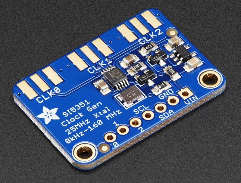
It's a breakout board with an Silicon Labs Si5351A that can output 3 diferent clock's.

And just in time after finishing the code for the computer controled VFO on the Arduino.

Plugged one of them to the Arduino and now have some RF using the supplied example on the library.

Now it's more coding so I can change the output from the Si5351 for the first mixer and product detector. Something tells me that it's not going to be easy...

I bough two of them since I am thinking in adding another IF to the "Trevo" transceiver and then create a "shift" and "width" controls by varying the BFO, VFO and the IF LO. I will try first to implement in software and them test, I'm sure gains on the different stages must be well defined. Anyhow will be easier in software than with cristal mixing schemes.

It must be two boards since the chip in fact only has two independent PLL's from what I've seen so far.

Have a great week!

Thursday, October 09, 2014

My Arduino think's he is an Yaesu (Arduino CAT controlled, VFO)


Here goes the basic code and details for the Arduino CAT controlled or Yaesu "emulator" for remote controlling a VFO from a PC.


I tested against "Rigresident" and "Commander v5.8.7" software using 9K6 on the serial port (Arduino USB serial console) and booth Yaesu 857 and 817 command set (are the same for all that matters).
The control of the VFO chip itself (Si570, AD9850 etc) is not implemented on the code, there are comments were it should be placed.  Consider the code as a base for your own solution.


If copy past of the following code does not work for you because of blogger formatting let me know, I can send code on email.

// Code starts here
//
// Basic code for remote control of an VFO base on the Arduino platform using CAT software or Hamlib
//
// Emulates basic functions of an FT857 (and similar Yaesu) in the Arduino platform from the perspective of the CAT software
// set mode, set frequence and get frequency only at the moment
//
// By: CT2GQV - Ricardo
//
// Licence: GPL - use according, in no way I will be responsable for the magic smoke you may get!
//
// Information sources: Hamlib, FT857.h from VE3BUX
//
// to be done: add s-meter reading and sending. Add code to control Si5351, Si570, ad9850/1 etc
// any help is apreciated

#include
#include
#include

// whatever lcd is used, might need some changes
// LCD control, SDA and SCL to analog 4 and 5 pin
#define I2C_ADDR    0x27  // I2C Address for my LCD, found with I2C scanner
#define BACKLIGHT_PIN     3
#define En_pin  2
#define Rw_pin  1
#define Rs_pin  0
#define D4_pin  4
#define D5_pin  5
#define D6_pin  6
#define D7_pin  7
LiquidCrystal_I2C       lcd(I2C_ADDR,En_pin,Rw_pin,Rs_pin,D4_pin,D5_pin,D6_pin,D7_pin);

// modes as going/coming from rig control, no need for hex since it will the last byte in the array, diferent story if it was the first....
#define LSB 0                          
#define USB 1                                        
#define CW 2                                           
#define AM 4                                             
#define FM 8
#define RTTY 10
#define PKT 12

// this could be done in a diferent way... see comments on the code about "to_bcd_be"
// ...don't remember coding so bad in the past years... oh well, get's the job done
#define HZERO 0x00                          
#define HONE 0x01                                        
#define HTWO 0x02                                           
#define HTHRE 0x03                                             
#define HFOUR 0x04
#define HFIVE 0x05
#define HSIX 0x06
#define HSEVEN 0x07 
#define HEIGHT 0x08
#define HNINE 0x09                                        
#define HTEN 0x10  
#define HTWENTY 0x20                                             
#define HTHIRTY 0x30
#define HFOURTY 0x40
#define HFIFTY 0x50
#define HSIXTY 0x60
#define HSEVENTY 0x70                                             
#define HEIGHTY 0x80
#define HNINETY 0x90

int incomingByte;   // for incoming serial data from rig control soft.
int counter_byte = 1; // just a counter for the bytes in radiocommand array
int radiocommand[5]; //  array to keep the previous commands from the rig control software...
int i; // just an aux counter
char a[8]; // will keep the hex to send to rig software when requests frequency vfo is in

// in the future get the next values (start up frequency and mode) from saved configuration...
//                 4 4 3,7 5 0.5 1 0 (this would be 443Mhz 750Khz and 513 Hz (show up as 443,750.51)
//                       8 5 0 5 1 3 ( 850 Khz and 512 Hz  (show up as  850.51)
int myfrequency[]={1,4,4,7,5,0,1,2,5};  // to rig control only first 8 values are sent...for vfo connected that a diferent story
int mymode = USB; // mode usb,lsb,cw,am,fm,rtty,pkt

// setup function of the Arduino
void setup() {
  
  Serial.begin(9600); // 9k6 speed, can be reduced.
  lcd.begin (20,4,LCD_5x8DOTS); lcd.setBacklightPin(BACKLIGHT_PIN,POSITIVE); lcd.setBacklight(HIGH); // 20x4 lines display LCD
  lcd.home(); lcd.print(" CAT controlled ");  // just dummy info, trying just to keep for 16 case lcd changes to 16x2
  lcd.setCursor(0,1);  
  switch (mymode) {case 0: lcd.print("LSB  "); break; case 1:  lcd.print("USB  "); break; case 2: lcd.print("CW   "); break; case 4: lcd.print("AM   "); break;
                   case 8: lcd.print("FM   "); break; case 10: lcd.print("RTTY "); break; case 12: lcd.print("PKT  "); break; }
  for (i = 0; i < 8; i = i + 1) { if (i==3 || i==6) {lcd.print(".");}; lcd.print(myfrequency[i]); } // print the startup frequency
////////////////////////////////////////
// put code here to initialize vfo connected to Arduino
///////////////////////////////////////
}

void loop() {

////////////// RIG CONTROL PART //////////////////////////////////////////////// 
 // do we have serial data?... 
 if (Serial.available() > 0) {
   incomingByte = Serial.read(); // read the incoming byte command from the serial line
   radiocommand[counter_byte]=incomingByte; // place the incoming byte on the array

  ////// let's start switching the commands sent from rig control software...
  
   // if the rig control software comand is 0x03 then send out current frquency by request of rig control software
   if (incomingByte==3 && radiocommand[4]==0 && radiocommand[3]==0 && radiocommand[2]==0 && radiocommand[1]==0 ) {
   // loop in myfrequency starting on the first vaule we have for frequency until the maximum of the myfrequency array (8)
   // if anyone has time to change the following this would be much better job with "to_bcd_be" from hamlib, basical convert to nibles and join and send...
   for (i = 0; i < 8; i = i + 2 ) { //loop all digits from 0 to 7 from the myfrequency array, join two by two and send the HEX value
       switch (myfrequency[i]) {
        case 0: a[i]= HZERO; break;  case 1: a[i]= HTEN;  break;  case 2: a[i]= HTWENTY; break; case 3: a[i]= HTHIRTY; break; 
        case 4: a[i]= HFOURTY;  break; case 5: a[i]= HFIFTY; break; case 6: a[i]= HSIXTY; break; case 7: a[i]= HSEVENTY;  break;
        case 8: a[i]= HEIGHTY; break; case 9: a[i]= HNINETY; break;   } // end switch first digit
       switch (myfrequency[i+1]) {
        case 0: a[i+1]= HZERO; break;  case 1: a[i+1]= HONE;  break; case 2: a[i+1]= HTWO; break; case 3: a[i+1]= HTHRE; break; 
        case 4: a[i+1]= HFOUR;  break;  case 5: a[i+1]= HFIVE; break; case 6: a[i+1]= HSIX; break; case 7: a[i+1]= HSEVEN;  break;
        case 8: a[i+1]= HEIGHT; break; case 9: a[i+1]= HNINE; break; } // end switch of the second digit
    } // end of the for loop to read frequency we are in and and convert to BCD
    // lets now send the frequency data to rig control software in this format a1a2.b1b2.c1c2.d1d2.ee (ee is mode)
    Serial.write(a[0]+a[1]); Serial.write(a[2]+a[3]); Serial.write(a[4]+a[5]); Serial.write(a[6]+a[7]); Serial.write(mymode); 
//////////////////////   
// no code is needed here because we are just sending the present frequency we are in
/////////////////////////////////////////////
   } // end send out current frequency
  
   // if the rig control software command is 0x01 then set frequency  whith the values sent aa.bb.cc.dd.0x01
   if (radiocommand[5]==1) {
         int tempo;           
         tempo = radiocommand[1]>>4; myfrequency[0]=tempo; tempo = radiocommand[1]&0x0f; myfrequency[1]=tempo;
         tempo = radiocommand[2]>>4; myfrequency[2]=tempo; tempo = radiocommand[2]&0x0f; myfrequency[3]=tempo;
         tempo = radiocommand[3]>>4; myfrequency[4]=tempo; tempo = radiocommand[3]&0x0f; myfrequency[5]=tempo;
         tempo = radiocommand[4]>>4; myfrequency[6]=tempo; tempo = radiocommand[4]&0x0f; myfrequency[7]=tempo;
         // print the new frequency we were requested to go to by rig control software
         lcd.setCursor(0,1);  
         switch (mymode) {case 0: lcd.print("LSB  "); break; case 1:  lcd.print("USB  "); break; case 2: lcd.print("CW   "); break; case 4: lcd.print("AM   "); break;
                   case 8: lcd.print("FM   "); break; case 10: lcd.print("RTTY "); break; case 12: lcd.print("PKT  "); break; }
         for (i = 0; i < 8; i = i + 1) { if (i==3 || i==6) {lcd.print(".");}; lcd.print(myfrequency[i]); }     
//////////////////////////////////
// put code here to set the new frequency on the vfo... ex: set_vfo(myfrequeny);
//////////////////////////////////
   } // end of rig control command to set a new frequency on the VFO
  
   // set mode command sent from rig control software
   if (incomingByte==7 && radiocommand[4]==0 && radiocommand[3]==0 && radiocommand[2]==0) { //rig control will set mode on the arduino
      if (radiocommand[1]==0){ mymode=LSB; }; if (radiocommand[1]==1){ mymode=USB;};
      if (radiocommand[1]==2){ mymode=CW;};  if (radiocommand[1]==8){ mymode=FM;};
      if (radiocommand[1]==4){ mymode=AM;}; if (radiocommand[1]==10){ mymode=RTTY;};
      if (radiocommand[1]==12){ mymode=PKT; };
      // will print mode on the lcd after mode change requested by rig control software..and also the frequency just to refresh the screen
      lcd.setCursor(0,1);  
      switch (mymode) {case 0: lcd.print("LSB  "); break; case 1:  lcd.print("USB  "); break; case 2: lcd.print("CW   "); break; case 4: lcd.print("AM   "); break;
                   case 8: lcd.print("FM   "); break; case 10: lcd.print("RTTY "); break; case 12:    lcd.print("PKT  "); break; }
      for (i = 0; i < 8; i = i + 1) { if (i==3 || i==6) {lcd.print(".");}; lcd.print(myfrequency[i]); } // print the startup frequency
//////////////////////////////////
// put code here to change mode ex; set_mode(mymode)
// if mymode = 1 (USB) then switch on digital pin 1...
// if mymode = 2 (CW) then switch on digital pin 2...
//////////////////////////////////
   } // end of set mode by rig control
///// end of pattern/command recognition part

  counter_byte++; // increment the position on the array read from the serial line        
  if (counter_byte>5) {counter_byte=1; }; // if we reached the end of the array.. that is previous counter byte = 5 and now 6 because we incremented before
 } // end of if serial avaiable cycle and command execution from RIG control software
///////////////// END / RIG CONTROL PART //////////////////////////////////////////////////

// put code on the next lines to read button/rotary press to change frequency, change mode etc..
// and other stuff....
/////////////////


} // end of main Arduino loop

// end of code


The LCD I used is this one (20x4  I2C connection):


I changed the code to use only 2 lines of the LCD since a 16x2 is more common than a 20x4.

LCD connection as follow:

GND from LCD to Arduino Pin Gnd (on power bus)
VCC from LCD to Arduino Pin 5v (on power bus)
SDA from LCD to Arduino Pin Analog A4 (on analog bus)
SCL from LCD to Arduino Pin Analog  A5 (on analog bus)

You can use a different LCD, just change the code.


Have a nice weekend!

Sunday, October 05, 2014

My Arduino think's he is an Yaesu

Having battling intermittently for the past two weeks to get an Arduino to "emulate" the Yaesu serial protocol I finaly got it, I can set frequency and mode from the rig control software on to the Arduino:

Setting the frequency:
 The Arduino picket up (My Freq:) and then I sent another frequency change to 446Mhz:


I didn't take the new frequency set picture (set freq) but it did worked. Mode "8" is the hex sent from the rig control software for FM mode.


Tried to find some other similar project and found none so have to make it myself, far as I know this is one of a kind! There are some projects but are to control an Yaesu radio from an Arduino, not the RIG CAT software to control the Arduino. The idea is remotely controlling the VFO of the "Trevo" transceiver (the one I've been building for the last year)
Will release the code if there's any interest and after beeing well polished... it will take time.

add: code: http://speakyssb.blogspot.ie/2014/10/my-arduino-thinks-he-is-yaesu-arduino.html

Have a good weekend!

Sunday, September 07, 2014

North Cork Radio Group Annual Radio & Electronics Rally - 2014

It was today.

I restricted myself to only small bits, even so I bring a little more than wanted to!


From top to botton and left to right: a mic and bnc connectors, a power meter ; bellow:
a bigger box with an 1.5Ghz capable mixer inside (MCL SCM2500) and on top a box with a circulator (1.4 to 1.7Ghz according to datasheet). I just wanted the aluminum box for other stuff but the mixer and the circulator might be interesting to go a litle higger in frequency from what I'm used to do. So for my record of a fully working transceiver is still way bellow on the 2m band.
The power meter got if for 5 Eur thinking that might have some interesting logarithmic detector inside...yes and no, it has two 1N5711 diodes and an double opamp making two separate detectors. I removed the original plugs (tv type) and replaced with a silver BNC and left only one of the circuits in place (they were dientical and can be selected by the top switch). I was powered by 15V, I placed inside a 10v regulator and now I have to calibrate to the new supply. The meter could be handy special because its small size. In the future might replace the inside with an AD8307 circuit. 
Not in the picture I bought 5 small pieces of PCB, always handy and two egg isolators for antenna wire. Again, looked at ladder line and didn't bough, just like last year, maybe one of this days I will finally build a ladder line antenna/aerial!

Have a great week!

Tuesday, August 26, 2014

Scope bandscope adapter

...Just some modules glued togetter:


 Signal on display is from a QRSS Kit at 14.200Mhz...


 placed very close to input since there's no positive gain in the circuit and the mixer was homebuilt.
 Lower channel is the trigger. Log detector is an AD8307 and IF filter (10Mhz) is incorrectly terminated....
(add: made some measurement: vpp on the ramp for the vfo is 3.44V. Min vfo freq is: 4.174Mhz and max vfo is: 4.196Mhz, that is around 22Khz and makes 2.44Khz by division. I was thinking the peak was a bit large but in fact should be correct)

...plenty of room to improve....

And... have a nice week!


Thursday, August 21, 2014

New oscilloscpe - Rigol DS1052E

...Yes, my third oscilloscope. First one, the "Kiotto" brand (nice crap of tech support) died some time ago. Then I bough a second hand "Hameg" HM307:


 (in need of some maintenance but still functional as long as I let it warm) which is on main shack.

This new "Rigol", I'v been thinking in getting it for almost a year, now was the time.
Here it is in all it's glory:


I am more productive building without an oscilloscope, only for some circuits that the wave form is important it will help me a lot, like the one in the picture.

Yes, if you want to know, the fan is noisy (I've seen server's less noisy) and yes you need to read the manual for more complex functions, for the default one just press the auto button. No, I will not try the 100Mhz hack for it....for now.
The scope comes with two test probes good to 6 Mhz.
The trace it's not as responsive as a crt scope but crt's can't do fft transformations or math on the input signals either.

I am almost sure the old Hameg will live longer since it can be repaired, the new modern equipments as soon as they have a problem, it's just a matter of sending to the bin.

Have a nice weekend!

Thursday, August 07, 2014

Front panel method


Decided for the first time to make a nice front panel, well, at least was the first time I succeed doing so.
Interesting enough is I made the front panel and a box before actually the equipment beeing fully operational and tested, so, now I have to make it work!


 The way as I made this was: made all the holes to the components, LCD and buttons, then printed the front panel as an overlay (trust me, it's better to print first and cut last, so you don't have to print many tests).
Before applying the paper I spayed prime on the aluminum panel, after dried used paper glue to fix and set the paper on top. Finally some varnish was spayed to give a more glossy look.

Because the prime was grey and the paper very thin (normal print paper) it got a slightly grey tone.
Another issue was on turnng the nuts of the buttons, with a plier, some small scratches were made.


The project it self is an arduino to select the frequency of the airband receiver I bough in 2013 in the Cork Ham radio rally, this one:


This receiver frequency is set inside by means of dip switchs on a MC145151 PLL and the idea of the project is to have an external box controlling the PLL so it can rapidly change frequency without opening the box.
Right now the code to select the frequency is working, only missing the output part and cabling to the PLL circuit. When finish will be posted here.


Have a nice weekend!


Wednesday, June 11, 2014

QRG - Trevo

Yup, it's possible to build a complete radio using only an multimeter as test tool but to know the exact frequency it's more practical to use a frequency counter.

Got myself a frequency counter kit, it will help me "debug" the VFO:


Now i'm on the 80 and 20m band (9 +/- 5.212)

Have a nice day!

Thursday, June 05, 2014

The "Trevo" works

Ok, I don't know in what frequency it his receiving, only I got my first copy of Morse signals from the ether!

The reason I don't know the frequency is simple, the only test equipment used so far is a multimeter.
After trying to figure it out the frequency of the VFO (I was suspecting that I could be receiving in the 40M or 80M band) I fired the qrss transmitter kit and set it for 3.580 Mhz, after tuning the VFO got my own test transmission (I was receiving some amateur Morse before).

The VFO (lower right on the image) is not the final design, just a quick lashed up design without great stability. Tuning is made by a varicap and a trimer cap, the two blue trimmers are for fine an coarse frequency set.


The only problems so far were:

* Incorrect publication, on the original article, of a component value on the bias of the BFO oscillator transistor which I discovered quick; the measured voltage was two low for bias and had reception for a second or so (after power on) before loosing it (was testing the BFO/product detector at 4Mhz since there's powerful AM stations around, now the BFO is back on 9Mhz)

* Thermal shutdown of the LM7912 (I'm using it so in the future I can add a 2n3055 with collector to ground) occurred on the makeshift power supply after some time of power on, now with more modules have to set another design to power the transceiver.

* Incorrect bias of microphone on the connection to the balanced modulator (still have to find out how a elect mic element does not needs power to give signal)

Work to be done:

* Decide on the VFO design
* Finish the transmit section
* Finish the band pass and low pass filters
* Adjust everything

That should be more one or two years at this rate!

Have a nice weekend.

Monday, May 26, 2014

FT-102 full line on desk

I finally had some time to assemble and test the new bought accessories to the FT-102.

Here's the result:


Now only some "minor" issues:

1- The HF antenna is broken (nothing to do with the radio tough)
2 -The accessories bough came with extended feet, the FT-102 didn't
3 - There are 2 birdies generated by the external VFO at 100Khz and 200Khz mark
4 - There's an offset of around 500Hz between the external VFO and the FT-102 counter (assuming one of them is correct, could not beat against WWV to confirm since the antenna is broken, see point 1)

How to address the issues:

1 - When I have time will fix it (not using this shack at the moment)
2 - Asked for the price of a pair of extended feet (got the reply while writing this; 5 GBP)
3 - Will investigate cable routing (signal is picked up on the antenna port)
4 - When I have plenty of time will adjust the thing

Another view of the setup:


Didn't tested the antenna tuner, assuming it's working.

Have a nice week!

Tuesday, May 13, 2014

New transceiver - Trevo

No, it's not the latest from the "East", it's not the latest from the brand that makes cooking ware.... it's simple the "Trevo", a new transceiver I'm building.

It's made in Ireland, were the water is free, (not anymore), by a Portuguese using mostly schematics from the rest of the world.... it can't go wrong....

The idea will be to have a medium performance transceiver for the everyday use, using some classic blocks without big fancy stuff. I'm building in blocks that at anytime can be changesd or replaced, also trying to use common components without compromising too much the performance. Most of the signal switching is done using relays (I might regret this in the future).

So far I made the following parts/modules:

*The BFO oscillator on the left, on the midle the mixer (ADE-1) and on the right the audio pre-amp chain. Isolated below, and still in the making is the AM detector

 *The IF amplifier chain on top, below on the left, the IF filters, one AM one SSB one LSB and one USB at 9.00 Mhz. On the right the first RF pre-amp and the attenuator.

*Bellow the audio amp on the left and on the righ just a makshift power supply, on top left an experimental mixer.
* The bandpass filtering section

* The mic amplifier on the right (741), SSB and AM modulator (by unbalancing) midle and left (MC1496).


Regarding the schematics, when I'm happy with the performance I will post them...just wait.


Since all transceivers have names/model, decided to cal this one "Trevo"; it could be the acronimouns for "Transmiter Receiver Evolution".... no, it's the Portuguese word for Shamrock which is one of the symbols of Ireland. I hope it makes sense....


Have a nice week and good luck!


Thursday, April 24, 2014

PRC-239-6X

Some time ago I bought one of this radios:


A military PRC-239-6X, 6m FM, not that I needed one just because I found it a fun design radio and was relatively cheap.


View of the power supply/regulator module and front panel:
And now the back with the belt support:

I also have the mic and tape antenna:


Since it was powered on probably 2 times , although it still works I might recycle it, at least the box for something else.... maybe one of this days.

Have a nice weekend!