Showing posts with label Power Supply. Show all posts

Saturday, November 19, 2022

High voltage supply for tube/valve tester

 A power supply for a future tube/valve tester


Main circuit for the positive side is similar to the one bellow (the top section),


 The filament circuit is similar to the bottom section.

 The negative supply is similar to the diagram bellow("Standard") with small adaptations to allow 2 different ranges:


 There's a separate transformer for each of the supplies; the filament the positive and the negative, also other separate on to power the voltage meters.

Was added a small relay controlled high voltage supply output so I don't get accidentally zapped, you need to constantly press enable button to have high voltage output at the terminals.

The internals:


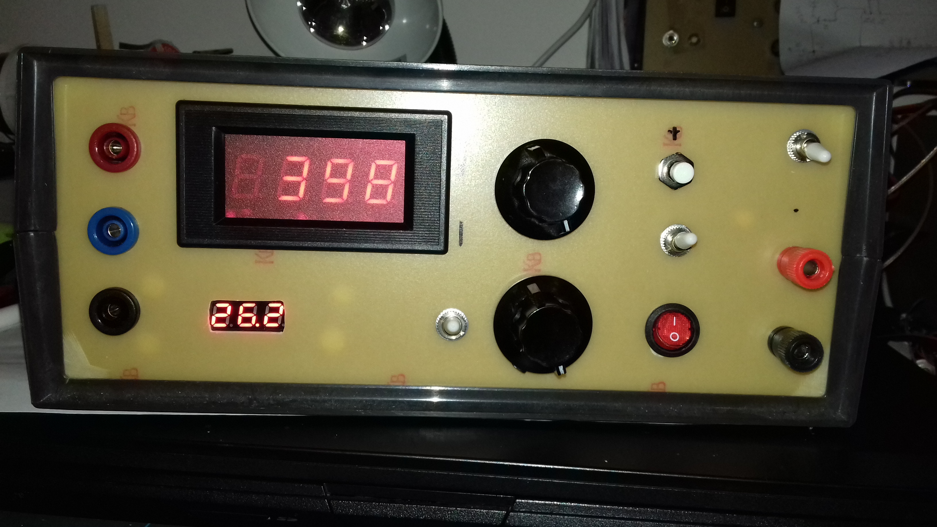
 Finished here:


Working during testing:


Now I still need the tube socket and metering part for the full valve/tube test set, eventually something like this (only the top section):


Have a nice day!


Saturday, May 22, 2021

Fan/temperature control for Agilent/HP6621A

 This power supply is a bit noisy with the fan being constantly on. 


Decided to change the fan status to come on only when temperature rise since it will be mostly used for small loads. 

The approach decided was the simplest one without much changes internally, a temperature activated switch for 30C inline with the fan supply (110V).

The switch was bolted to the heat-sync in the small available space and tested before drilling so it would not touch the lid after closing.


For example it would not fit on the following position:


The end result:


No schematic here, just placed the switch inline/series with one of the fan power cable line.

keep in mind that the thermal switch used is a normally open one (NO) and not like the most common ones, normally closed (NC), used in home appliances, like toasters and grills, also called thermal cut out switch.  It closes on reaching 30C.

The switch is just on the heath sync of power supply A, that will be the most used output. For output B would be just a matter of paralleling another thermal switch. The power supply it self has temperature control for thermal shutdown, that will be the second "line of defense" in case anything to go wrong and also the transformer itself resonates so it will be not a full quiet power supply.


Have a nice day!


Monday, May 11, 2020

GPIB - Agilent/HP 6621A

A new one for the "software" pile, using GPIB, Linux and Python.

In the past I placed some example on how to control the outputs of the Agilent/HP 6621A using the Arduino USB to GPIB converter, now, using a "proper" GPIB board to get the current delivered on the two outputs in graphical form and from the command line to set the same outputs.


The code output, along with the startup icon on the background, bellow; "1" is the current of output one and "2" is for output #2:

...not much going around at the time of the display.

Since the voltage will not change in most of the testings I do I didn't included the set voltage, anyhow I have an external meter better suited for easy reading than the LCD on the equipment. The meter also includes output jacks extended from the back of the PSU unit.

The panel meter used was a "conversion" of a 0 to 250VAC type to 0 to 25VDC in this post.

The Code to display the output current (every 1s):

=== code start gpsu.py

#!/usr/bin/python
import Tkinter as tk
import pyvisa
import time

rm = pyvisa.ResourceManager()
inst = rm.open_resource('GPIB0::1::INSTR')

counter = 0
def counter_label(label):
  def count():
    global counter
    counter += 1
    current1=inst.query("IOUT?1")
    current2=inst.query("IOUT?2")
    label.config(text="1:"+current1+"2:"+current2)
    label.after(1000, count)
  count()

root = tk.Tk()
root.title("Agilent 6621A - Iout")
label = tk.Label(root, fg="light green", bg ="dark green", font = "Helvetica 18 bold italic")
label.pack()
counter_label(label)
button = tk.Button(root, text=' EXIT ', width=45, command=root.destroy)
button.pack()
root.mainloop()

=== code end gpsu.py


If you need to set output on the PSU from command prompt you can use this one bellow (setoutput.py):

=== code start setoutput.py

#!/usr/bin/python
# sets output 1 or 2 from Agilent 6621A power supply via gpib
# needs pyvisa
import time
import pyvisa
import sys

rm = pyvisa.ResourceManager()
# gpib card 0 address 1, change to your instrument address
inst = rm.open_resource('GPIB0::1::INSTR')

if len(sys.argv) == 3:
 print("Setting: ")
 print "Output #",
 print sys.argv[1],
 print "to ",
 print sys.argv[2],
 print " V"

 if sys.argv[1] == "1": # setting output number 1
  inst.query("VSET1,"+sys.argv[2])
  print("..done!")

 if sys.argv[1] == "2": # setting output number 2
  inst.query("VSET2,"+sys.argv[2])
  print("..done!")


# number of args not given currectly
else:
 print("")
 print("Not enough arguments")
 print("")
 print("setoutput.py ")
 print("")
 print("ex: setoutput.py 1 5.00")

# voltage2=inst.query("VOUT?2")
# current1=inst.query("IOUT?1")
# current2=inst.query("IOUT?2")

=== code end setoutput.py

To get all (current and voltage) from the PSU use the following code (getoutput.py):

(previous screenshot showing the output 1 and 2 voltages being set and the collected the current values along with the current)

=== code start getoutput.py

#!/usr/bin/python
# sets output 1 or 2 from Agilent 6621A power supply via gpib
# needs pyvisa
import time
import pyvisa
import sys

rm = pyvisa.ResourceManager()
# gpib card 0 address 1, change to your instrument address
inst = rm.open_resource('GPIB0::1::INSTR')

if len(sys.argv) == 3:
 print("Setting: ")
 print "Output #",
 print sys.argv[1],
 print "to ",
 print sys.argv[2],
 print " V"

 if sys.argv[1] == "1": # setting output number 1
  inst.query("VSET1,"+sys.argv[2])
  print("..done!")

 if sys.argv[1] == "2": # setting output number 2
  inst.query("VSET2,"+sys.argv[2])
  print("..done!")


# number of args not given currectly
else:
 print("")
 print("Not enough arguments")
 print("")
 print("setoutput.py ")
 print("")
 print("ex: setoutput.py 1 5.00")

# voltage2=inst.query("VOUT?2")
# current1=inst.query("IOUT?1")
# current2=inst.query("IOUT?2")

=== code end getoutput.py


Hope you find it useful.

Have a nice day!


Saturday, March 14, 2020

HP/Agilent 6621A removing fan noise.

This "mod" not only takes all the fan noise from the Agilent/HP 6621A as it goes a step forward, disables it completely...


I got this power supply to equip the lab with something professional grade, it is in fact a really nice power supply with lots of features but has a fan that no one can stand being near by. Imagine a vacuum cleaner to have an idea.

In the past I did a box to bring the two output from the back to the front along with a voltage meter (converted one of 250v to 25) for visual reference of the output, it's easy than looking at the LCD, below indicating 5V on output 2:


Back to the fan noise, initially was thinking in making a thermostat control to actuate only when needed but I'm not going to use the equipment that often so just disconnected the fan, now I can only hear the hum from the massive transformer, that is still noticeable and something I didn't eared/noticed before. To have an idea the power supply weights around 17Kg

The supply has an internal thermal shutdown circuit so hopefully that will be enough for day to day and low current supply. There is also a small gap on the back panel that latter on I can put a switch to enable the fan without the need to open it.

Here's the fan connection:


and without the plug... end of the fan noise:

Interesting enough the fan is a 115V version, here's the diagram:

as you can see the fan will connect to mains transformer terminals 4 and 5 (120V), clever design.


The massive transformer inside:

and one of the two power modules, amazing engineering:


I might revisit this in the future if I decide on thermostat control.

Have a great day!

Saturday, May 26, 2018

MIC5205 (LB30, KB30) Low noise regulator, increasing voltage output

Yes, made a mistake, ordered a mic5205 low noise regulator 3.0V output model, when I should had ordered the 3.3V version for a project in the "pipeline".

The typical application for the IC is like this:


This particular IC is not absolutely needed on the project but why not testing new devices....I should had read better the IC reference chart when ordered... should had been MIC5205-3.3BM5 instead of MIC5205-3.0BM5, as you can see, after the dash there's the output voltage, as on the data-sheet:


Looking at the internal diagram (fixed output version on top):

..it looks pretty much a "standard" series regulation schematic so there's room for change the output voltage and that can be done the following way:


By inserting a drop voltage from ground, at the IC GND pin, to a new ground it will "force" a "floating" ground at the anode of the 1N4007 diode, being the drop voltage value at the diode the increase in the schematic output. Any diode will work and depending of the forward voltage there will be the matching increase on the output. In my case the output is now 3.5  V from the original 3V, and that is inside the 2.6 to 3.6 V specs for the devices being powered by this IC downstream.

I'm really not a big fan of the SMD format since I don't have all the proper tools to solder them, anyhow since it's getting harder to get IC's in standard DIP format, in the future, will try to get more up-to-date on surface mount.
Here's a size, comparative to a resistor and the soldering iron tip.


I had to solder it with extra solder and then removed the excess with solder wick.  


Have a nice weekend!


Sunday, April 15, 2018

Mains power meter and rig energy consumption.

Got this meter some time ago, idea was to place in a box with a current switch to act as mains shack power outlet, letting me measure actual power consumption of the equipments when in use.

Meter was bough out of the "bay", rated to 20A, it has 2 input and 2 output power terminals. Here Some initial testing with it:


It also has cumulative power consumption besides the other values.

I placed, this Easter when in vacation in Portugal, on a standard electrical box along with the circuit breaker rated for 6A, sure I will not need more at the moment.

The advantage is I can shutdown all the shack power from one single point while also monitoring mains values.

And bellow the measure rating for some of the equipments currently connected.

Winer is the FT-102 without tube heater on, add around more 30w for that. "Only" in RX mode:


Then the FT-307/FT-107:


..same power as the light bulb in the first picture.

Lowest power consumption goes for the "Speaky" transceiver:


The "Speaky" power supply, a Yaesu one, takes 1.8W so the actual power is lower than the 8.4W:

Both the FT-307 and FT-102 have internal power supply.

The big surprise is the Kenwood power supply, I suspect there could be some leakage at the caps .as a reason for the almost 14w.


I didn't check transmitting power consumption since the FT-307 has a fault in the PA and the FT-102 is now developing a receive fault, I suspect a cap in the AGC path. Will have to fix one of this days.

This is a good reminder to run more time on the "Speaky" transceiver so save energy.

Have a nice day!

Bench power supply ( part II )

After part I, here's part II for the conclusion of the bench power supply.

It's a dual adjustable power supply based on LM317 and LM337, 3 terminal using adjustable positive (LM317) and negative (LM337) regulators.

Basic circuit is this one after some changes on the original one and it's similar to the ones on the datasheet of the regulators:

And the finished product in the box, the right half of the box with voltage meters displaying output voltage.


The lower voltage meter although showing a positive value is measuring the negative part of the circuit. From white post (0 V / GND) to black one (- V).
I can enable the main power output on the left only also (part I blog post):

or both at the same time:
 For the USB output, in the middle, there's no need to measure since it's allways 5v and it's allways on.

Inside the mess looks like this:
 The smaller transformer is for the dual supply and the big one to the single output.

 The meter modules on the panel (small green pcb), are feed from the output at the binding posts, so, with voltages lower than 4.5V approx will go blank.


Have a great week!


Friday, December 29, 2017

Bench power supply ( part I )

This is part I from the build of a small bench power supply.
It's going to be 3 supplies in 1, one from 3-19V (build bellow), a 5v USB output and a variable dual rail implementation of the LM317/337.
The first one, already finish, is using an LM723 implementation, nothing special, just picked the first schematic that seamed viable and built it.
This power supply it's just to avoid having to resort to the 13.8V one from the radio since it will be used for small circuits testing.

Here's the outcome (left size finished minus buttons and voltage display, latter on that):

The USB out (in the midle) it's going to be useful for testing Arduino projects without fear of frying the USB port on the computer, it's just a garden implementation of the LM7805 with two 100nF caps on the input and output.

The schematic that I used for the variable supply was the one bellow (from here):

I used a TIP3055 and TIP31 instead since I didn't had the specified ones, the 600 Ohm resistor was replaced with a 680 one.

Bellow a similar schematic with more comprehensive details of the current and voltage controls (from here):

Inside stays like this:
More details with the TIP3055 heathsink (piece of metal) in place:
and the view to the front panel back side:
The box used was one on sale on the local electronics shop and even include a transformer inside, the only downsize was that you had to build your own front panel, nothing some PCB and elbow grease would not sort out:

Not perfect but works. Bellow another picture during front panel build:
The switch most to the left enables or disables the output, handy if you see something smoking while testing and it cuts faster than the main power switch due to charge on the filtering capacitors.

Enjoy the weekend and see you probably next year!