Monday, June 29, 2009

VHF Preamplifier


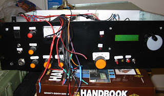
....Here is the infamous VHF preamplifier that let me discover the problem in the antenna input plug, no wonder it worked better with the antenna cable in short circuit that with it open, the external cable was really working as the antenna.

Now it works nice, at least improves something on the signal level, without the amplifier I have for instance S4, with the amplifier goes to S5, not bad but not great either...could be good for marginal signals.


You probably can use the orignal design, I started testing with the coils but then remove them until I found the problem was the antenna input. Mine is working like on the schematic... less is more :)

Now the airband receiver continues to not working well, will buy another TDA1072 to check it it's broken.

Sunday, June 28, 2009

New airband input filter part (II)

...It's probable that the filter and amplifier are working... today I was brewing another pre amplifier and after much testing and not understating why a piece of wire working as an antenna was working better than the external antenna I found the plug from the cable of the external aerial was broken.... I don't feel like to talk more on this subject....

p.s. It's quite probable that the "broken" TDA1072 was also related to this plug "problem".

Saturday, June 27, 2009

New airband input filter

New filter...new problems....

Built the filter in this schematic:


"My" filter stops after C8 and without R6 and C9, basically everything that is connected until the 2SC transistor.

After making the coils and soldering everything.... power to the circuit. Input connected to my airband antenna and output (right end of C8) connected to my TM-D700.... it went from an amplifier to and attenuator... before the filter insertion I had S2 on a continuous transmission frequency, now I barely can hear the transmission.....could be the coils... made a new set and solder them.... a litle beter but no increase in signal, only S0! Tryed some varicaps in paralel with the 82p capacitors some triming and nothing.... could be the transistor..but it's brand new and was tested in my multimeter....
Next time i will probably test every tuned circuit agains the antenna analyser, that way will have a beter idea of how far I am from expected ressonance frequency.

RF is fun.... the emiter terminal of the 2sc transistor is about 1cm long, is connected to the ground but if I placed an trimer capacitor bettwen ground and 3mm of the lenght of the terminal (from ground) there is some notiçable change in sound from the receiver......oh well, giving up for the weekend...probably not.

Thursday, June 25, 2009

Airband receiver...the saga

Yup....I think I broke an TDA1072 (AM demodulator et all). Trying to improve sensitivity on the airband receiver decided to try the NE602 as a front end... some soldering later (I never had tested the Si570 connected to the NE602) it was ready to rock....powering up and some hash sound (noise) changed "vfo" to the local FM station....and nothing...just before I notice the s-meter geting a litle higher than usual....normaly is a good sign, more IF, more signal... but nothing other than noise, time to check connections.... everything was alright except I forgot to solder one of the NE602 pins... soldered and nothing... some more tests and nothing.... you can imagine the rest... testing...soldering loop...
Ok the NE602 is not as easy as that, at least with the TDA IF, let's connect again with the TA7358.... now a circuit that was working is not any more and since the common part in the equation was the TDA1072 I assume it is broke or at least part of it... had no more patience for the day so I will leave it for further testing.

Anyhow, found a nice airband filter for a NE602 front end an probably will use part of it to connect the TA7358 maybe will improve things a little better.

Bought 2 MC3361 for making an FM IF, at least part of the airband schematic will be used if not for AM at least for FM.

Also going to make a small DC receiver, crystal controlled on 10.7Mhz so I can verify the 10.7 IF output, unfortunatly my scope is broken so other testing equipment has to be made to get more info.

Tuesday, June 23, 2009

The airband receiver squelch revisited

....Impossibly to find a stand alone (and simple) squelch in the internet and in books that I have.

Had to cut and past from a bigger online receiver design and rework some changes.
Since last time I studied op-amps somewhere last century I forgot that ideal op-amps are not real ones, that's why there are so many models. The original design (first rework) was not working due the specific nature of "real" op-amps... the 741 didn't worked as expected.

It's a simple comparator circuit without hysteresis.... that is done by the lack of precision of the adjustable potentiometer movement (backslash et all), if it was a multiturn, probably hysteresis was a good thing to have.

The schematic:


There is space for improvement, for instance if the signal is to strong it will not block the audio (max signal value no enough), changing the 1k ohm resistor for a bigger value will allow that, in the other hand it is nice if your friend is calling you on frequency near your house....

And the video of it working (not a very explicit example since exactly when I was testing all the channels were with signals opening the squelch level I set):


0-500 Khz converter to 4Mhz


No big science here, the venerable NE602 working as a mixer....again...
This was part of a NAVTEX receiver experiment. NAVTEX signals are around 490 and 518 Khz so I first built an PLL oscilator for those frequencies (for a DC receiver) but the PLL never worked like I wished so the idea was first to make the conversion to 4Mhz and then built a direct receiver around that frequency. Never did built the receiver but tested the converter against my TS-50 and it did received great.
The PCB schematic is not exactly the same in the paper (different input filter) but any design with the NE602 will work.

Monday, June 22, 2009

Read the datasheet

Why am I writing this... because my aviation band receiver was not receiving what I wanted, only some aircraft's passing by, nice music on 88-108, some packet on 144.800 but I couldn't get VOLMET (meteo info) on 126.400 but my TM-D700 could receive on the same place and with an inferior antenna (it's bad when your own homebrew receiver is inferior to a commercial unit that took years to develop....)

I allways say: "RFTM" (read the friendly manual)......but never do it myself :)

After testing numerous TA7358 schematic configurations I found on the internet, finally decided to look carefully at the IC datasheet and go some conclusions:

"Wide supply voltage range: Vcc = 1.6-6v": some schematics have a Vcc of 8 or 9V ??? IC max supply at 25ºC is 8V .I tested to 12v....it survived ,Inow set it to 6V

Look at the schematic in the datasheet and you will see a tuned circuit at pin 3 (rf amp out): Some shcematics don't have a "by the book" tuned circuit...have something else...my circuit now has one and the internal rf amp is "tuned" and tunable. Removed the external rf preamp since there is no need of a rf preamp connected to pin 1 (rf preamp in), just a bandpass filter. If you put a preamp before it will overload the poor IC expecialy in hurban environment

After some testing and configuration change on the TA7358 I now can receiver VOLMET, with some noise in the background but readable, now it's time to improve even further...

I found out that if you trow a TA7358 to a PCB it will work, limited but will work, but if you whant to get all the juice from it you have to push hard and test a lot... will post some more news later.

If you copied my receiver schematic you will have a limited performance.. I told you so...never trust an internet schematic...

....and the squelch design is also broken... also working on a new one (my own design).

No photo today! Read!

Sunday, June 21, 2009

144Mhz to 24Mhz downconverter

Some past project I built but never put to work... maybe some day I will check again on this one, I remember the oscillator worked. I am sure it will work the rest of the circuit.
basically you have a 40Mhz oscillator and by mutual coupling you get the third harmonic (120Mhz) that you put on a NE602 as mixer against 144Mhz input with a preamp and on the output you get 24Mhz (144-120).

Schematic and prototype photos:


It's summer time


It's summer time.... and impossible to do anything with the temperatures that are getting to this country, the global warming guys are correct.... I need a shack in the south pole, from now on I will reduce the brewing... I will be heading the beach more often!

This is the display of the temperature when I arrived at my shack in the attic. The outside sensor is between the tiles on the roof....

The good news is I found a can full of components.... some NE602, some KA358 (what the hell was I thinking in brew with those IC's..), 2N2222, 2N3904, 2N3906 and a lot of resistors and capacitors I have now to sort....

Saturday, June 20, 2009

Another SWR meter (part II)


...Forget the LM3914 for swr display, will be used as a VU-meter, couldn't get the simple circuit to work as it should, except when de swr was high (full scale on the display), intermediate values... nothing, zero, nada! I was doing something wrong for sure also the rf circuit was not the same on the original drawing.

Anyhow the RF part on this swr meter is working fine, in fact will replace probably another one that was also running fine...

This is a standard design, nothing new except I changed the number of turns on the transformer, normally the schematics give 10, I placed 16; on the antenna analyzer I have flat swr until about 50Mhz and 1.5 on 170Mhz, I am sure it will not work nice at those frequencies.

Calibration is easy, place on any frequency on "AM" or FM push the PTT and adjust the forward reading to the power you have (by rotating the FWD pot), if you have a 100w transceiver then adjust to 40 on the scale (that's probably your "AM" power), reverse the connections on the in/output antenna and transceiver press the PTT and adjust the pot of the "REV" part so the meter also gives 40. It's set, easy hum?

Diodes used were not the ones in the schematic, it was the BAT85 diode. I am sure it will work with the 1N4007.... very limited but will work...

On to the schematic:

Wednesday, June 17, 2009

Another SWR meter (part I)


Yes! Not happy with so many unfinished projects and with already two swr meter's made and also without the need of a third one I found a nice little project that was begin g to be made :)

This one instead of a cross nedle meter or a simple micro amp meter uses the famous LM3914, funny thing is I had never used this IC before.
The RF front end will be based on another one that gave me nice results, will post that another day.

Since I removed the 100uA fron one of the swr meter's to use as signal meter on the HF transceiver (beeing built) this is the right project to use in it's place. The PCB will fit on the space left in the front panel of the meter that's the why of the round placement of the LED's.

Now the nice part, schematic photo or photo of the schematic...


p.s. Do not duplicate this circuit, I am having a little difficulty putting it to work as expected (the LM3914 is way to sensible in this configuration...), and by the way, the LED's color/sequence are reversed....that's why I say, never trust a schematic done by others, including myself :)

p.s. II ...I forgot I was doing the rf pickup and the display on two spearated boards so the grounds are separated...you have to have the ground loop..... anyhow it's still not perfect I an making more tests.


Tuesday, June 16, 2009

Toroid info and meter adapter


Having some toroids in the junk box and also having some difficulty selecting the best one for the job I decided to grab some information about those scary little things....

You can have a guess on what type you have by testing the inductance of a given number of turns at a given frequency. My idea is to build a litle adapter for my inductance meter and make a nice little table ( read: handwritten) with the given number of turns/frequency/toroid type/inductance. It will be easier with an adapter since holding the toroid to an PL plug is not the best practice, my "inductance" meter uses a PL plug.

In the photo some data on toroids and the future adapter "schematic" ( in the midle of the photo)...
Basically 2 crocodile claws to hold the toroid turns soldered to a PL plug.

Monday, June 15, 2009

About the "Speaky"


What gave origin to this blog was the build of the "Speaky" HF transceiver, see: http://www.qrpproject.de/UK/Speaky1.htm
After the initial rush to finish the kit, it is now stopped, some time ago I made some tests but had a problem with the frequency counter so I decided to rewire everything.
Hope to get some courage soon to put the "Speaky" on air or at least in the operating desk. The "major" problem with the "Speaky" is the documentation, it's plenty, but in German and English and with the schematic scattered in different pages so allways back and forth for checking connections. Will make one schematic from all the part's so it can be easy readable and easier to debug all the connections.

Sunday, June 14, 2009

Radio exhibit - Photos


As promised I went to see the radio and fishing electronic exhibit equipment in Peniche...
On the first photo one station I always liked, nice color, nicely built and bullet prof.

Here are some photos of equipment in the exhibit:

SSB Radios (2182 Khz Is the emergency frequency, that's the only frequency I ever had memorized).


Radars


Echo sounders


Radio direction finders


Test equipment for repair:


I have other photos, will post as soon as possible.
Tomorrow will try to solder something...

Friday, June 12, 2009

In stock


Managed to recover an acceptable stock level on some components. This time I doubled the minimum stock.... if I needed one capacitor I bought 2 :)
Some rg174 cable and some shielded audio cable for pot connections.

This electronic hobby is getting expensive, spent 15.00 € on what you see in the photo.

Thursday, June 11, 2009

Noise generator


Simple to build signal noise generator


Mine was based on this design: http://www.qsl.net/wq1rp/nb_instr.pdf
I left provision for the bridge but right now is working like the design in: http://www.n0ss.net/noise_source.pdf the only difference is the output (doesn't go to the bridge)

Put's S9+20 on 30m! :)
The box is normally closed but that way you couldn't see the PCB :)

HF Bandpass filter


In the process of building one multiband transceiver from a mix of different designs I set for this bandpass filter: http://www.gqrp.org/technical1.htm.
Having the Toko coils getting dust for long it was time to start building it....
Case you didn't read some previous blog entry... I am out of stock in some components namely several low value capacitors....anyhow started to put some "cans" and making the first test in the 30m band, why? Because at 10.100 there is always there a big signal, if it's not, everything is closed :)

Placing the filter inline with my TS-50 I started to "tune" the coils for maximum signal at my interest frequency (10.102Mhz), it's one way of doing it, another way I already tested was with the antenna "analyzer" in the input and a 50 Ohm load on the output. Now the interesting part, I can get around 50 Ohm load on the meter (R=3 X=50) but SWR does not drop bellow 10.... I am missing something for shure...
Another possible test I did: Placed my homebrew noise generator ( It's the first time I use it for something except for checking it's working) at the input of the filter and then the ouput connected to the TS-50.... you can see the signal meter with only the noise generator and with the filter inline. 2 dashes lower in signal, should this be normal or not I would have to have the s-meter calibrated...tho see attenuation... etc...etc... well at least this filter is kind of working, further tests will be done at the end. Must read more about rf testing.

Direct connection of noise generator to radio:


The bandpass filter inline between noise generator and radio (best optimization on the filter built):


Now the big question is: are the Toko coils correctly placed (with the correct pinout, reading the schematic I think they are).... I can answer that but will have to invert pinout and make some more tests....if someone knows the answer please leave a comment.

p.s. Found the same schematic a little bit more explicit, I think my component placement is correct after all.
Schematic at: http://home.hetnet.nl/~gbakelaar/kank.jpg

Wednesday, June 10, 2009

Radio exhibit

Went to Peniche were I lived some time in my life (some nice photos of Peniche and near by here: http://www.flickr.com/photos/vitor107/sets/1419666/ ).
Walking around the local museum something got my attention, a marine radio and electronic equipment exhibit. Since I was on short time and didn't have my camera (only the cell phone) I will pospone the visit for another day and post here the photos.
For short time I worked for a company that did repairs on boat electronic equipment so probably I will see similar equipment I worked at that time, still recall those "Sailor" from Denmark marine SSB and VHF radios, great piece of equipment.


Anyhow, walking a litle more and I went for what I was on, visit the "Vera Cruz" boat, a trustfull replica of the boats that almost discover half of this world by the Portuguese sailors.
It's a very simple boat but still nice to see how was life aboard 500 years ago, well, this one at least had a HF vertical antenna and radio. It's on the rear of the boat, try to find it bettwen all those cables!
(tip: the antenna is between the rear flag and the lady in red)


Now on to homebrew business.... I hope tomorow to have same time to solder the HF bandpass filter board, even without the capacitors and only the Toko coils.

Tuesday, June 09, 2009

Out of stock

....Yes, I know! Lousy stock management....I should buy as soon as stock level arrives to 100 units... by reference :)

Today during a free time at lunch I went to the local electronic shop, they are open during lunch time wich is nice.... they changed their open hours, closed lunch....not nice, you don't do that to a desperate homebrewer...

Anyhow it's nothing critical except the next 2 days are bank holidays ... now only Friday I can get the components..... I have no free time Friday... bloody hell ! everything is against me!

Well, I will prepare some PCB's for a bandpass filter for the HF receiver I'm building and probably will rebuild some old projects...

Sunday, June 07, 2009

Airband 10.7 AM IF


It's weekend...so... relax....

Done this board during the morning and it's still not finished (give me a break, it's weekend) but you get the idea.

455Khz filter was salvage from a Chinese store radio but it's too wide, will try in the future buy one better for the job, never the less it works. IC is a TDA1072 and schematic is similar to the datasheet (http://www.nxp.com/acrobat_download/datasheets/TDA1072AT_CNV_2.pdf) excepto on the 455Khz IF transformer that was "removed".

Now it's just a mater of small details and I can put the receiver on the shack. Anyhow I am allready thinking on adding an 10.7 ssb IF and one for FM (any ideias on a simple 10.7 FM IF without the MC3362 ?)

Friday, June 05, 2009

Airband squelch


....Did you think there was no provision for a squelch? Of course not! It's the most important feature of any receiver!
This schematic came from an online bigger schematic, I just change for what I need.
I will only test at the end but looks really simple and should work... or not.

Placed the IC and components in the audio amp board since there was space there and there's no need to make a board only for a simple circuit.

The squelch part is the one on the left in the photo in the right part is the audio "filter" and "power" amp.

There's 2 components missing (and forgot to place the 10M resistor) that I had none in the shack, 4k7 resistor and 10k pot. Must go shopping, my stock is getting dangerously low. I did think of replacing the BC183 for an BC547, but I found 2 around, probably 20 years old... hope it works :) gain was 193 (I think) on my tester.

Thursday, June 04, 2009

Airband first mixer


Another day...another module!

Today I Made the first mixer for the airband (and not only) receiver. It was easy, just a question of separating the circuit from the original board and solder again in my new standard modules PCB.
Now the question arises, what will I do with the PCB inside the computer power supply box.... the idea now is to put there (is already ready for that) one of my very low budget frequency counters (see previous posts) and brew there a direct conversion receiver or even one regenerative receiver I have laying around in the shack.

Attention: Pin 5 on the TA7358 should go to ground (not connected on the photo schematic).... please, never trust others schematics :)

Wednesday, June 03, 2009

Airband rf preamplifier

Done!

No big deal here, the preamplifier is working... sort of... with the antenna connected to my Kenwood TM-D700 I have S4, with the preamp on in circuit and same antena I have S5, funny is with the preamp in line and no power I have S2, so the last coil in the circuit is a very good antenna!
This results are really subjective...since I have no means to test deeper I have to trust the S-meter...

Bellow the antenna, the circuit in test (with the magic cable adapter) and the schematic.
I changed some components from the original drawing... when I have all boards connected will try to improve the design.


Seting some standards

After some making circuits with different type's of support (including no support) I decided to set myself an standard on PCB experimental board's so everything looks the same.
I buy PCB on 20*30 (cm) chunks so after some complex math....(rest should give 0) I set on 10*6 (cm) which give's me 10 smaller PCB's, enough for a 5 conversion super duper heterodyne transceiver :)


From left to right some of the boards in fabrication process: RF pre-amp (to be brewed), First mixer, attenuator, audio amp.

I placed in each board 2 holes for fixing inside their box.

Monday, June 01, 2009

The cable adapter


...It's monday... not a very good day :) But I had a nice Sunday with lot of brew, so now a little thing for those who are still trying to wake up!
If you're like me, when you need to test something (connect diferent meters) you have millions of adapters and cables for different connectors like bnc to rca to pl to uhf to sma...you name it I/you have :)


Most testing's I do are with BNC and PL plugs so I brew this adapter to use with PL and will brew another to use with BNC (my frequency counter uses BNC)
To do this I used a piece of PCB and with an hacksaw make sone cuts so I can connect the input and output cables and bettwen something I am going to test, this avoids soldering directly on the tester cable.


Above: Ready for testing the attenuator

I think the photos are self explanatory, if you have questions... don't send any email :)