Are all my wishes to this blog readers.... and maybe some Eur/USD/GBP/etc to spend on electronic components :)
Here's the light modulator in QRO version...and a better reception "antenna"!
Will post more details next year! It was made today.
Have fun!
Saturday, December 31, 2011
Thursday, December 29, 2011
6500K AM transceiver
After the build of the 6500K AM modulator I had to do a compatible receiver. Following the tests with the green LED's I thought they were the right candidates to "antennas"...
before the receiver part build I made a small audio oscillator since it's easier to test with a steady source than a mic, this one oscillates around 1100 Hz.

The oscilator "out" after the pot and 0.22 cap connect's directly to the transmit driver input:
 There is nothing simpler, not high performance of course...
Receiving part is just the 2 green LED's connect directly to the input of an LM386 amplifier with 200x gain. Standard from datasheet and no input level pot.

And here the prototype in test:

I got 1 inch range before signal get's to low, in fact signal is just near the noise floor of the LM386, an preamplifier would increase a little bit but using LED's as light receivers isn't the most efficient way of doing things, an LDR or a phototransistor will do a better job for sure. Anyhow it's just a proof of concept....
Have fun!
Wednesday, December 28, 2011
Powered by led's II
Another test with LED's, last time I didn't tested all in the junk box... now I tested the green variety, 2 in series.
The light emitter in the video is my Christmas self present, one LASER pointer that doubles as a small lantern with 2 bright white LED's. Local electronic store doesn't store LASER led's so for 2.5 Eur I had one, just have to disassemble it for further tests in light transmission. The optics su!"# big time but it works for small scale tests.
I did test also a Ge diode with a glass envelop and it did respond to the LASER light giving 21mV, it was an OA90 type I think.
Trying to scale the led's for power harvesting isn't interesting, it's cheaper to buy a small solar panel (from my head calculation) and also other solutions, will try them one of this days.
Monday, December 26, 2011
Electronics - Zener
I post some schematics, some are mine, mostly aren't.... I do understand some basics on electronics but as year's pass somethings are getting forgotten so here's an exercise to remember....
Zeners are tiny little funny devices.... they sit quiet in their room until someone drops them a voltage over their rated value, basically like diodes but on a bigger scale (voltage wise), and then they tend to conduct some electrons.... I never thought it was so difficult to explain what components do..... let's say a zener is the equivalent of a series connection of diodes but connected the other way around, polarity wise.
So let's see a tipical circuit with a zener:
 There's a power supply, Vs a resistor R, a zener (that weird diode) and the famous (or not) NE602.
So let's see from an engineering point of view.... the potencial diferencial sum (basicaly the sum of voltages) in a circuit should be "0" (zero)... if not you are creating an energy monster :) but this doesn't matter for the zener subject...just for puting arrows in the circuit case some old teacher of mine sees this...
On we go...
Let's supose we need to stabilize the voltage in the NE602 at 6.2V (just because it eases some math and circuit simplicity). It's also nice to know that the NE602 needs about 2.5mA (0.0025A) of current to work and we have a power supply of
13.8V (most of the time) and our zener can witstand 41mA (normaly more but this is a tested current value from the datasheet and we whant things cool)
Now, we can do this in two ways....
The worst case scenario and the low power scenario...
* The worst case scenario:
Let's say we can have a problem in the power supply and voltage can raise to 24V
We would have to drop some 17.8V in the resistor to maintain 6.2V in the NE602 so our resistor should be (U/I) 17.8 / (Iz + Ine602) = 17.8 / (41mA + 2.5mA) = 409 Ohm...
Power dissipated in the resistor is: 0.77W
Power dissipated in the zener is: 0.25W
So what about when we are runing the nominal 13.8V:
We would have to drop 7.6V in the resistor (13.8V less the zener 6.2V), if our resistance is 409 Ohm then the current is: U/R = 7.6/409 = 18.5mA that is 2.5mA for the NE602 and 16mA in the zener diode.
Power dissipated in the resistor is: 0.14W
Power dissipated in the zener is: 0.099W
* The low power scenario:
Let's save the planet and make low CO2 emissions:
We have a good 13.8 power supply the NE602 consuption is still 2.5mA and we will give just 5mA for the zener (he must do something and still have some margin for power supply flutuation)
Our resistor is now: U/I = (13.8-6.2) / 7.5mA = 7.6 / 7.5mA = 1013 Ohm
Power dissipated in the resistor is: 0.057W
Power dissipated in the zener is: 0.031W
Much less power than on the worst case scenario...
...let's just see what max voltage the circuit can withstand...
We use the same 41mA max on the zener and 2.5mA on the NE602 so voltage on the resistor is R*I = 1013 * 43.5mA = 44V plus the 6.2 on the zener that's: 50.2V
And what if the voltage drops: let's acount only for the NE602 current so the voltage in the resistor is 1013*2.5mA = 2.53V plus the minimum for the NE602 that we consider is 6.2 then the voltage in the circuit should be no less than: 8.73V.
Conclusion:
The worst case scenario let's you drop more on the power supply voltage (409*2.5mA is less than 1013*2.5mA).
The low power scenario covers you more on over voltage and has less power consumption at normal operating points...you choose!
Have fun!
Friday, December 16, 2011
Mussels...

The problem of being a home brewer/DIY/having the knack ,on electronics is that sooner or latter you end up thinking you can build/make anything...
One of the first things outside electronics I did was changing the car oil, the sparks and air and oil filter.... it went well...but now it's something different, after watching some Australian "Master Chef" episodes I convinced myself that cooking is easy....compared to harmonics/IP3/band filters, etc...
Here's a local recipe with Mussels (they were also "caught" by me).
You will need:
*Mussels
*Garlic
*Onion
*Olive oil
Just pour some olive oil, some chopped peaces of garlic and onion on a pan, take it to the stove in a slow cooking position.
As soon as the onions and garlic start to get a light yellow color (means they are starting to get cooked) pour the mussels inside, keep a low power on the stove, cover the pan and let them cook in the steam. Do not put water or salt, they have plenty of salted water inside. Let them cook until they have the shells fully open.
The mussels should be fresh an alive.
Here's the outcome:
 It's more of an entry or "tapas" than a meal.
A circuit in the next post... or another recipe!
Friday, December 09, 2011
Mains filter, results
I told you I would write about the mains filter performance after the little VDR issue (blast off).
Well... did it worked?.....did it?...... n....no! Can't win all the time!
I'm sure the mentioned filter would work in minor interferences from mains, so the filter will be put in line with the transceiver power line (it's 230V AC powered).
I am not the first one to have issues with switching power supplies since by their nature they are an RF source and this one is a beast, 4A at 20V, normal laptops are have half the rate in current, I guess this computer is not very economical in power consumption.
When removing interferences that you suspect are from a power line there is some simple stuff one can do:
*Put a power line filter: Didn't worked in my case. If the power is DC sometimes a simple capacitor in parallel or an inductor in series will do the trick (low pass filter), capacitors "don't like" voltage change so do the inductors with current.
*Invert the power plug terminals: This will work if the source problem is unbalanced (power line wise)
*Some ferrite cores around the power cables. I've used this method wen using the Si570 RF generator close to some testing boards and it works (Now when using the Si570 I power it up from a separate power supply).
*Build a Faraday cage: Will work as long as that any "air" space in the gaps is smaller than the interfering wavelength... but for my case I suspect the interference is getting in from the antenna cable since the FT-102 it's self is build in a metallic "Faraday cage". I discarded the hypotheses of the interference getting picked by the antenna since it's 10m away, never the less further tests will be conducted...like removing the antenna cable and the microphone.
I didn't tested yet was to put the laptop power supply inside the filter cage and earth blindage exiting the power cable or even moving to another plug (it's to far away for connecting the laptop to the screen monitor).
*Put and isolation transformer (230V/230V): That is expensive and I would prefer to put again the small computer previous used that I know causes no interference.
Well...the saga will continue....I will test more this weekend.
Monday, December 05, 2011
6500K AM modulator
...Or a "spread spectrum" AM modulator, 390 to 750nm wavelenght, or 400 to 790 THz..... or a white LED AM modulator... now you get it?
Following some LED experiments I wanted to try some light comunication, so decided to do one of the basic forms of modulated light communications, AM, for good or for worst the idea was just to have some fun....
Here's the transmission part, when time permits (I still have a huge backlog on lower frequencies projects) will make some companion receiver and put a mic on this "transmitter".
 As you can understand, first I did the schematic and then the final draw on paper...
Any NPN transistor should work but more led's (more power!) will require a more robust transistor, the speaker was just to ear the modulation noise (touching the LM386 input pin), I had no mic at hand.
The pot set's the bias point, and the led should be always on (a steady carrier!?), changing bright by modulation.
LM386 gain was set by an 10uF cap between pin 1 and 8 as standard design.
You can ear noise and see some modulated light in this lousy video:
Have fun!
Saturday, December 03, 2011
Powered by led's

I do like led's but aside the fact they are nice to show power on in circuits I only did some minor tests with them. One of the experiments some time ago was to use a led as a poor and small replacement for a solar cell, yes led's can generate small amounts of energy. Some can sense radiation and other types of PN junction can be nice for temperature sensing (like 1n4148 diode)... normaly components have more than one function you know?! The classic example is a resistor used as a camera flash :) One time action of course!
Next images you have an infrared led, (I think, since I don't remember the specs or even when it was bought) the outer case is light blue and emits no visible light when direct biased.
Here in reverse connection getting some direct sun light.
Two of them in series should give 1.4V althoug on a very small current, this multimeter has 10M of internal impedance but if you put some in parallel you end up with a very small power supply as long as the sun shines...Here's the "power" from a white color paint!:
 Incidently this gave me the idea of using one of this for a very crude Sun photometer.... maybe one of this days...
And in the dark:

This led was the best one I tested, other standard types gave worst results.
Have fun!
Tuesday, November 22, 2011
Mains filter
A friend gave me one of those new computers....a tablet...:)
 ...never mind the missing screen (there's an vga plug), it works and it was cheap!
My idea was to put Linux in it and use at the weekend shack, it came with windows something installed and for now will stay that way (sure not for long since I'm a bit allergic to that OS).
After some psk and rtty decoding apps installed, decided to hook it up to the FT-102. I was a rainy day and I was getting a lot of interference, I thought it was the weather but after shutting down the computer I notice the interference had gone and the only (confirmed) source was the computer power supply! Rat's! Something had to be done....
So I came up with the idea of making a mains filter idea. The other option includes a Faraday cage for the power supply or getting another computer.
Here's the assembly of the interference filter for the mains power supply:

well....did it worked?.....no and not tested yet, after powering it up (I should had tested before closing the box) the VDR blew up, I guess that it was underrated or I didn't looked very well to the schematic of the donation computer power supply were I removed it and probably the VDR was not on the mains line and was not rated for over 230V.
Now that I removed the broken VDR I have to wait for the next weekend to conduct further tests.
Here's the schematic used:
 ..never mind the VDR (it's just for spike protection), it's not installed at the moment. If you duplicate this, get capacitors rated for at least 500Vrms, the ones I used are rated 1KV and came from a computer power supply.
The number of turns it's not critical as long as they don't create a lot of impedance on the mains 50Hz....I guess something bellow 1000 turns it's ok :) The idea is to create some high impedance on HF and VHF.
I also placed a ferrite core (the ones used in computer power cables) around the cables as a "won't hurt, probably will help" option.

The white output is the filtered one (it's an old household mains plug), the other two are input and a not filtered output, they came with the donated box (a broken computer power supply).
There's no reason for this schematic do not work at least reducing the level of interference. If it reduces all ,then it's a bonus.
 ...never mind the missing screen (there's an vga plug), it works and it was cheap!
My idea was to put Linux in it and use at the weekend shack, it came with windows something installed and for now will stay that way (sure not for long since I'm a bit allergic to that OS).
After some psk and rtty decoding apps installed, decided to hook it up to the FT-102. I was a rainy day and I was getting a lot of interference, I thought it was the weather but after shutting down the computer I notice the interference had gone and the only (confirmed) source was the computer power supply! Rat's! Something had to be done....
So I came up with the idea of making a mains filter idea. The other option includes a Faraday cage for the power supply or getting another computer.
Here's the assembly of the interference filter for the mains power supply:

well....did it worked?.....no and not tested yet, after powering it up (I should had tested before closing the box) the VDR blew up, I guess that it was underrated or I didn't looked very well to the schematic of the donation computer power supply were I removed it and probably the VDR was not on the mains line and was not rated for over 230V.
Now that I removed the broken VDR I have to wait for the next weekend to conduct further tests.
Here's the schematic used:
 ..never mind the VDR (it's just for spike protection), it's not installed at the moment. If you duplicate this, get capacitors rated for at least 500Vrms, the ones I used are rated 1KV and came from a computer power supply.
The number of turns it's not critical as long as they don't create a lot of impedance on the mains 50Hz....I guess something bellow 1000 turns it's ok :) The idea is to create some high impedance on HF and VHF.
I also placed a ferrite core (the ones used in computer power cables) around the cables as a "won't hurt, probably will help" option.
The white output is the filtered one (it's an old household mains plug), the other two are input and a not filtered output, they came with the donated box (a broken computer power supply).
There's no reason for this schematic do not work at least reducing the level of interference. If it reduces all ,then it's a bonus.
Saturday, November 12, 2011
New 10m radio
I don't have much time to do QSO's, in fact time is short even for soldering.... but I have a new radio.... A "Dragon" delta force.... don't you just love the names some manufacteus give to radios? There's also the same radio under the "Magnum" brand. Probably one of this day's someone is going to build the "Kalash terminator" 10m mobile.... :)
Here's the lousy photo:

10m was hot today, I've heard a lot of QSO's and almost pushed the ptt to answear a CQ call from the USA...maybe tomorow!
My first impression on the rig is a positive one, it works and receives nice, vfo operation is not easy on 1khz step since it counts from 1 to 9 but then returns to 0 without increment the 10's Khz...! It's not build like Yaesu, Kenwood etc, in term's of knobs material and front panel (didn't looked inside yet) but enough for the intended function, a receiver for some dowconverter's I will build.
Saturday, October 08, 2011
FM crystal radio
I'm back!...Along with the lousy photos and the rusty English...
Having already build a lot of receivers with different approaches I have never tried FM with a "crystal" radio. Now is the time.
This is a simple circuit and honestly I wasn't expecting much performance but is fun and helps getting some momentum for future builds.
I can only get two very faint stations and with an external amp based on an LM386, my "crystal" earpiece I guess is not crystal....
My implementation

The schematic was "borrow" from here. Go on, see the original and nice implementations on that site.
Original schematic from the author site

L: 5 Turns of 1mm silver wire on an "Edding 3000" pen (around 12mm), diode connects to 2.5 turn (half the coil), spacing is around 2mm
D: OA90 or 1N34 (not sure, it wasn't marked) I tried several glass diodes and results were similar.
R: 150 K
C3: 18p
C1: 82p
C2: used one trimmer of 25p (80pf on the original schematic)
Antenna was around 25cm of wire and the 2 station's received are less than 8 km from the shack.
Have fun.
Having already build a lot of receivers with different approaches I have never tried FM with a "crystal" radio. Now is the time.
This is a simple circuit and honestly I wasn't expecting much performance but is fun and helps getting some momentum for future builds.
I can only get two very faint stations and with an external amp based on an LM386, my "crystal" earpiece I guess is not crystal....
My implementation

The schematic was "borrow" from here. Go on, see the original and nice implementations on that site.
Original schematic from the author site
L: 5 Turns of 1mm silver wire on an "Edding 3000" pen (around 12mm), diode connects to 2.5 turn (half the coil), spacing is around 2mm
D: OA90 or 1N34 (not sure, it wasn't marked) I tried several glass diodes and results were similar.
R: 150 K
C3: 18p
C1: 82p
C2: used one trimmer of 25p (80pf on the original schematic)
Antenna was around 25cm of wire and the 2 station's received are less than 8 km from the shack.
Have fun.
Wednesday, September 21, 2011
Summer...
Sorry for not posting for the last few months but honestly I've been very busy.
Some 20 years ago I took the training in beach lifeguard, then I did some work on the beach in the following years as a summer job. At that time the training was valid for 5 years and I didn't renew it until this year.
This time, (20 years later) it was not easy from a physical point of view to make the training, most of my colleagues weren't even born when I did my first lifeguard summer on the beach.
I was the oldest in the class (but not the slowest swimming) although my time in the 400m is a little more than the double of the current olympic record :) anyhow I'm not thinking in going for an olympic medal
In June I was counting only to work some days replacing some colleagues on leave but I was offered full time in a near by beach so I end up doing all the summer season from 15 June to 15 September ence not having much time for this blog.
 Partial view of the beach
 The beach dog with the lifeguard hat and the yellow flag!
By the way in all the beach's were's a lifeguard there's a pole with a flag system for sea water conditions: green for good conditions, swiming is allowed; yellow for moderate conditions were swiming is not allowed but a bath is and red for dangerous conditions were beeing near the waterline is dangerous and is forbiden to go to the water (we have some tolerance during a red flag day).
 My observation point and some rescue equipment.
 During training! Why swim when you can go by "boat"? Guess who am I in the photo! :)
In the end all went smooth and I only had to do some small rescues.
Now I am slowly getting back to electronics and to this blog. Stay tuned!
Saturday, September 17, 2011
What's this ? III
While I don't get time to make a more useful and tangible electronic construction here it goes another "what's this" question....:
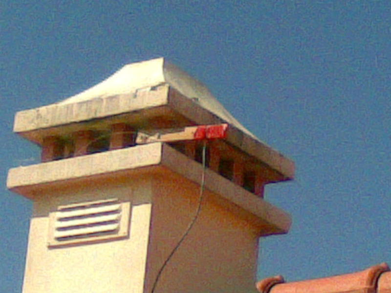
What type/model is this and what's the frequency range?

From the last post, here it goes the image on reference point GPS receiving antennas for error correction on GPS signal.
 As usual in Peniche there's always a seagull on top of something...
What type/model is this and what's the frequency range?

From the last post, here it goes the image on reference point GPS receiving antennas for error correction on GPS signal.
 As usual in Peniche there's always a seagull on top of something...
Saturday, April 30, 2011
What's this ? II
Here's another question, this time I know the answer...

The location is "Cabo Carvoeiro" (Cape Carvoeiro) located near the city of Peniche and of course the building is a lighthouse so that doesn't count as an answer, the antenna is a T type being the top part made of 2 parallel cables (lenght is 92m height is 27m), so could be probably a simple T with more bandwidth or sort of a terminated loop. There's also the possibility of beeing 2 antenas in redundance! Sory but I don't have more exact technical details.
The question is: what's the purpose of the antenna?
Anyhow the late antenna is almost as good as the HF one I putted in my alternative shack.... made in 20 minutes...
 can't get more simple than this...2 pieces of wire forming a dipole. Not perfect but much better than using the VHF antenna (it was for reception only!)...
Meanwhile I have been busy with other stuf so you have to wait for some more solderings... maybe next week.
Monday, April 18, 2011
World Amateur Radio Day
It's today!

The IARU theme for the 2011 World Amateur Radio Day is:

"Amateur Radio: The first technology-based social network"


...some do take it to the extreme!

have fun!
...some do take it to the extreme!
have fun!

Tuesday, April 12, 2011
What's this?

I haven't had much time for soldering so here's just a litle radio related post to keep the blog updated.
One of this days I went to the city park with my daughter for some fun and in this public space there's a nice little plane, it's there for the time I remember, for some time neglected now it's on a more proper shape. Beeing an ham, couldn't help from spoting some radio related parts.... but there's one I don't know what is it maybe someone can tell me:

The white cap look's like an insulator for the HF antenna at least it's very similar to the ones used in boats but the bullet shaped big device on top I could only guess it's some sort of radar or direction finding antenna inside, honestly I don't know, maybe someone knows....
The plane it's a Beechcraft DS 18/C 45 under "FAP" registration number 2508
Friday, April 01, 2011
100 W on the cheap
I spend some time yesterday thinking in today's build up.
Having read a post with schematics of compact fluorescent lamps I thought what could be done with those components.
Searching in components specs I noted that the MJE13001 transistors have an TF of 1000000000mHz so that's qualify them to be used in an HF amplifier, also their absolute voltage rating is in the order of 400V (collector to emitter).
I didn't planed to use the 400V but instead a more conservative 110V.
I also found that the toroid present in this lamps (first schematic on the site referred) it's similar to those used in broadband transformers (type 43 material) so will be used also.
Remember that voltages present could be lethal so take absolut care building this stuff.
Here's the schematic:

You should absolutly place a bandpass filter since transistors are working near saturation ence increasing harmonics.
Also place a a cover in the assembly before firing the power because they will get a little, just a little bit hot.... also usefull to remove hardware interferences :)
you can reuse the 1 Ohm resistor from the lamp and place them in the emitter of each transistor, reducing a little bit the output power to around 50W according to my readings.
So here you have from 5W to 100W with a light bulb and 2 power transformers!
Photos of the prototype will be placed tomorrow since I run out of cell phone battery. that allways hapens to me in April first.
Sunday, March 27, 2011
Day at the beach
Like most Sundays I go for a visit at my parents house.
The day usually begins with some sort of computer problem I must sort out...today it was no exception, the monitor of one of my father's computer didn't turned on, after the normal cable debug I fixed it really fast, exchanged the monitor and putted the old one in the things to fix later or for parts.... while I debugged the problem turned on the FT-102 on 20m band for some listening, and hell, even with the vhf dipole connected the contestants were putting 55, 57 on the southern Europe... who cares about QRP?! Anyhow, Im not a big fan of contests so headed to the beach.... much better, althoug the temperature was not that high, around 18ºC... :)
Here's something for the Eskimos:

Meanwhile the tube/valve direct conversion receiver already works but I am having some impedance mismatch at the rf mixer output so will have to fix it without hopefully putting a, rare around here, audio impedance transformer.
Have a nice week!
Friday, March 25, 2011
ECC82 Downconverter
I bough a spare ECC82 valve when I built the ECC82 regen receiver, already tried a valve VFO (worked), now decided to tryout a valve down converter as a first test to a tube direct conversion receiver.

Basically one half of the ECC82 is running as vfo then there's a single balanced mixer and will be an audio amplifier using the other half of the ECC82.
Interesting thing is that this circuit worked first time, I even forget to count the turns in the mixer core, the rfc was the first coil I found from an old PSU and the mixer output termination was the first small cap I found...
Signal out is not much but hell what do you expect from a lousy mixer made from a binocular core and 2 diodes and 4m of cable laying in the floor working as antenna...
The oscillator was running at 6.7Mhz and I was listening on 365Khz so one of the received frequencies was 7.067Mhz... I promise a schematic soon.
Add: here is the schematic used:

Thursday, March 17, 2011
Inside the sat-finder

Being a curious "animal" decided to have a look inside the sat-finder, probably the only equipment I own that never had been opened for "evaluation".
Here's the outcome:


There's some common components an LM358 opamp and a "C1C" component I could not identify or find info about, probably a dual diode or some transistor but it's marked as U1... so it could be also an IC. It's for sure the first stage for measuring the signal from the line.
Found very few schematics about sat-finder but here are some links:
This one also used an LM358: http://www.khazama.com/project/satfinder/default-en.aspx
Homebrew but it could be very close to what's inside..
and this one: http://www.neazoi.com/echochanceller/Satellite_Finder.gif
Tuesday, March 15, 2011
75 Ohm cable
Joachim's made a post about the use of 75 Ohm cable for ham radio. This is not the first time I see references to this subject but it's the first time I serious think about it.
In a first view I think it should be ok at least for reception or for moderate power transmission beeing impedance match just a small issue. I didn't checked all types of cables and ratings but it's somehow obvious.
This type of cable (75 Ohm) is normally used at TV/Satellite frequencies hence it should be good for HF to VHF and for sure UHF/SHF... but keep in mind that usually there's a mast amplifier or a down converter near the antenna/dish and that makes all the difference. The amplifier compensates attenuation losses and signal to noise ratio degradation!
If we look on the economic side then lets all jump and use 75 Ohm, the price difference it's brutal!
Here's a quick chart on some cables comparation with prices in the local electronics shop.

Now some quick tests with the MFJ antenna "analyser":

Keep in mind that I only used 1m cable length for the tests, I am sure beaviour with bigger cable lengths will be somehow different.
Let me have a little spare time to make some more tests, I have a spare 75 Ohm cable from the shack to the "antenna farm" that will be tested for sure.
For those who live in apartments with some restrictions on antennas it should be easy to justify a white cable going to the roof, just say it's for the satellite dish.
Have fun.
Monday, March 14, 2011
New shack + New VHF TX
I'm currently making some tests with the 21.4Mhz filters bought in last ham fair for an Si570 based VHF FM transmitter. Tests are promising and looking good so probably a final schematic in the next few days.
Here's some images on progress so far:
 The original schematic, bellow.
Right now after some changes the tuned circuit on the 10.7Mhz oscillator/ FM modulator (21.4Mhz) is now on a red toroid. The output of the ne602 has an output coil of 6 turns on the NE602 side (pin 4 and 5) and 1 turn for antenna matching (amplifier strip later) hopping to give 1500/50 impedance conversion...or near :)
 21.4Mhz filter is connected to the NE602 via a 10nF cap, so does pin 3 to ground. The 100K on the oscillator collector was removed. A small cap was added from the top the tuned circuit to the ground, there's a 56pF cap in parallel with the ferrite ring, resonance viewed by the dip meter is around 22Mhz, the red variable cap should put it on 21.4 after tuning.
Even with the 21.4 filter and the output coil I still have small harmonic leakage on the Si570 frequency - 21.4 * 2, that is: the frequency I hope to transmit (Si570 frequency - 21.4Mhz) minus 21.4Mhz, or Si570 frequency - 4 * 10.7Mhz :) Did not make yet tests on other harmonics. Si570 oscilation frequency is on the high side for that matter.
Mean while I arranged a secondary shack at my parents house, they were kind enough to prepare some extra electricity plastic tubing, when the house was built, from the shack to the rooft. That way it's easier to install antenna cabling. Unfortunately not all weekends I pay them a visit but it's nice to know that I am radio ready there case needed. At the moment I only have an VHF antenna tuned for the marine band but I left there a balun and some wire ready to deploy on a simple dipole form.
here's the setup:

Later on will get a wood rack on top of the FT-102.
Tuesday, March 08, 2011
Tube/Valve receiver... the schematic
..And the finished product...


..Sort of, there are still somethings to improve like putting a volume pot and antenna coupling. I didn't found yet the optimal antenna setting so will improve it in the future.
The schematic used:
 My valve/tube is the ECC82 which is an European version of the American 12AU7
Reference articles from here and here
Monday, March 07, 2011
Chamada Geral / SDR SHORT COURSE
Well, this post is not exactly about building something, instead about some interesting things being done locally (country wise that is).
Some years ago when I was a kid (I'm still one) there was a TV program about ham radio in the state television. I remember seeing some episodes but the radio bug was not yet very present, maybe those programs had triggered that, can't remember now.
Anyhow thanks to some hams those episodes are now avaiable in the internet. For sure most readers don't understand Portuguese but an image is still an image.
By the way "Chamada Geral" is "CQ - Calling all" translated to Portuguese.
Here the links to some episodes.
Chamada Geral Ep.01 : http://vimeo.com/20142175
Chamada Geral Ep.02 : http://vimeo.com/20147144
Chamada Geral Ep.03 : http://vimeo.com/20401248
Chamada Geral Ep.04 : http://vimeo.com/20401611
Chamada Geral Ep.05 : http://vimeo.com/20719705
Chamada Geral Ep.06 : http://vimeo.com/20719872
Chamada Geral Ep.12 : http://vimeo.com/20578250
Some more are being processed to upload.
Now the other subject...:
There is going to be held in Aveiro - Portugal an "SOFTWARE DEFINED RADIO HARDWARE SHORT COURSE"
Dr. Jeffrey Pawlan (W6KBL, WinRad creator/coder) will be presenting this short course.
It's during the week of 15 to 18 of March in "Instituto de Telecomunicações – Pólo de Aveiro" (Telecomunicacion Institute - Aveiro)
This short course has no cost and it's open to everyone, be it a radio amateur a university student or any other person.
Just because of a logistic matters there is the need to make an inscription that you can do with Luis Cupido (CT1DMK).
I personaly would like to go but don't know if I have the chance. Aveiro is 133Km from my QTH so it's not that far but it's more than one day.
Here's the agenda:
 Looks very interesting
And a litle map to locate you.

Saturday, March 05, 2011
ECC82 (12AU7) 12V VFO
Now that I de-freezed, on to work:
Found a nice article on a 12AU7(ECC82) vfo here, decided to try out the circuit using less lethal voltages (I had my fair share of electric shocks if you know what I mean).
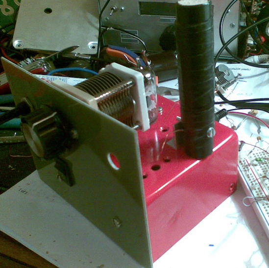
Here's the prototype:

...admire the beautifull wiring work... and circuit...you can find a clear one in the article link provided above.

It works! The only hard part is to make the a coil for it. Mine was done with the cientific methot of trial and error...oscilates around 800-1200khz but I intend to make one for 5-5.5Mhz.
This was just a proof of concept but working with 12V supply and no buffer it can deliver about 0dBm measured from my NCY (Not Calibrated Yet) AD8307 power meter.
It takes a little to get into oscillation due to valve warming as you can see in the video:
Having time and a nice box to put it, looks like a nice little external vfo for one of my vintage HF radios....one of this days....
Found a nice article on a 12AU7(ECC82) vfo here, decided to try out the circuit using less lethal voltages (I had my fair share of electric shocks if you know what I mean).
Here's the prototype:

...admire the beautifull wiring work...
 and circuit...you can find a clear one in the article link provided above.
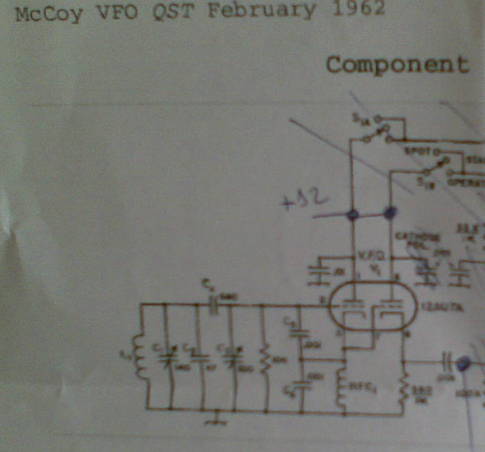
It works! The only hard part is to make the a coil for it. Mine was done with the cientific methot of trial and error...oscilates around 800-1200khz but I intend to make one for 5-5.5Mhz.
This was just a proof of concept but working with 12V supply and no buffer it can deliver about 0dBm measured from my NCY (Not Calibrated Yet) AD8307 power meter.
It takes a little to get into oscillation due to valve warming as you can see in the video:
Having time and a nice box to put it, looks like a nice little external vfo for one of my vintage HF radios....one of this days....
Subscribe to:
Posts (Atom)