Sunday, August 30, 2020

5LO38I CRT XY Oscilloscope

 Finished today the XY scope based on the 5LO38I CRT tube. It was working for some time but wanted to correct the voltage for the deflection amplifiers and missing a regulator, it was directly connected to the bridge rectifier, now has the required 7805 and 7905 regulators for the positive and negative voltages on this part of the circuit.


It's nothing special, it's based on previous experiments and adding now the deflection circuit. I have no space in the box to add a sweep circuit so it's kept as a generic XY display and not a full oscilloscope.

Because of the lack of shielding on the tube some re trace is seen, also does not help the lack of shielding on the vertical and horizontal amplifier input. As can be seen a bit here:

A bit more visible on the horizontal line.
Also during construction I had to reposition the power transformers because if near the CRT side will influence a lot on the trace quality. You notice that as soon as the power is taken, the dot became much sarper while the power supply caps still hold the charge.

Inside the unit:


The schematic is the one bellow except I added a 7805 and 7905 after the bridge rectifier to make the 5V for the op-amps:


Doing a Christmas tree with an Arduino:

... still had the inverted Y channel at this point.
Bellow the same on the Rigol DS1052E:


 That's it,

Have a nice day!


Sunday, August 23, 2020

GPIB - Rohde & Schwarz URY / URV5 Millivoltmeter

 Having the URY millivoltmeter decided to code a small utility to collect data via GPIB using Linux. As far as I know the URY is functionally the same as the URV5 being the URY a version for a specific marked, this software was tested only on the URY with Linux GPIB and Python.
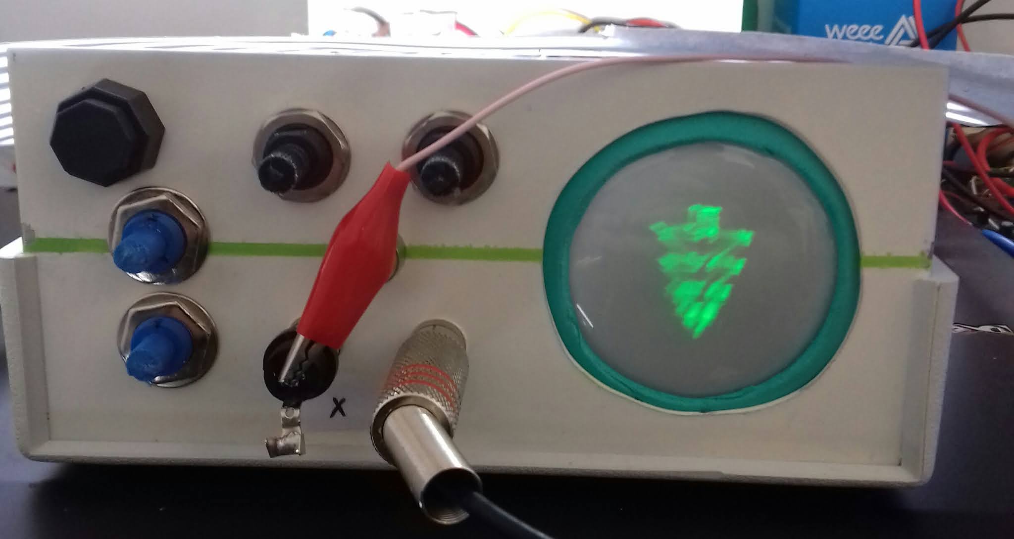
The meter:


The probe used for testing:


The graphical output along with the launcher icon:


The code for the above software:

===
import Tkinter as tk
import pyvisa
import time
# read power from channel A of the R&S URY millivoltmeter
rm = pyvisa.ResourceManager()
inst = rm.open_resource('GPIB0::12::INSTR')

counter = 0
def counter_label(label):
  def count():
    global counter
    counter += 1
    inst.write("IA,U1,KA0,F3,PA,F3,X1")
    result=inst.read_bytes(21, break_on_termchar='\r\n')
    result=result[9:] # remove the first 9 characters
    label.config(text=str(result)+" dBm")
    label.after(1000, count)
  count()

root = tk.Tk()
root.title("   R&S URY channel A  ")
label = tk.Label(root, fg="light green", bg ="dark green", font = "Helvetica 18 bold italic")
label.pack()
counter_label(label)
button = tk.Button(root, text=' EXIT ', width=35, command=root.destroy)
button.pack()
root.mainloop()
===

A screenshot in case formatting on blogger changes the code:


Made also a utility to get data via command line, could be handy for scripted collection. To get the values from channel B instead of A the code is only different on the instrument query string. The query is also only for dbm output, if you need any other unit or parameters do change the inst.write string.

Code for channel A:

copy/past version bellow:

===
#!/usr/bin/python
# get the power of channel A on R&S URY milivoltmeter

import pyvisa
rm = pyvisa.ResourceManager()

inst = rm.open_resource('GPIB0::12::INSTR')
inst.read_termination = '\n'
inst.write_termination = '\n'
inst.timeout = 5000

try:
  inst.write("IA,U1,KA0,F3,PA,F3,X1")
  exception = 1
  result=inst.read_bytes(20, break_on_termchar='\r\n')
  print(result)
except: exception = 2

if exception == 2:
 print("ERROR")
 exit()

===

Output example:

The query string for channel B:

In case no probe inserted you will get the "URY PB NO PROBE" message

Usage example along with code and diff for channel B:


Hope it helps.

Have a nice day!


Sunday, August 16, 2020

Wavetek 3001 signal generator repair

 Got this Wavetek 3001 signal generator just for testing the FM deviation meter since I haven't here my other signal generator and it was the cheaper unit that could generate a signal changing the deviation I could find in the usual online flea market.


Was expecting it to be fully working but unfortunately the listing  didn't matched the reality. Instead of sending it back I decided to try an fix it.
It was not giving any output and the indication meter for the output signal was not moving, also touching the back right panel where the power supply dissipation is, it was getting alarmingly hot after some seconds of power on. Testing the power lines for the + and negative 18V it was showing close to 0V... so either the supply was dead or there was a short. Because it was the two supply lines I suspected initially the output transistors of the supply.

 Looking at the service manual and some web resources was easy to see the 18V power supply lines in short or not working could be due the usual short electrolytic capacitors.

Two great resources I could find with a lot more information than this post are the following ones:

http://k5jxh.com/wave-tek/3006.html from K5JXH for the repair of a similar unit, a Wavetek 3006

and:

http://users.monash.edu.au/~ralphk/wavetek.html by Ralph Llimek on a repair of also a similar unit, Wavetek 3000

In my repair the only hard part was to find which module is the one at fault, if not multiple. That was my approach because looking at the power supply I could not find any fault (top right part vertical PCB).


My approach was to removed 5 random ones and see. I choose the first 5 on the bottom from left to right. What I did also was to put labels on all the cables for future reference although after unbolting them and turning the box upside down they started to fall with the cabling attached, saving me some time. I was lucky the first time, with 5 modules removed it was back to life, that is, there was no longer a short on the power supply and the output metter moved, then I installed one after the other until find the culprit, it was module M29-2, see bellow.


The modules are easy to remove from the chassis, just unbolt the bottom screen and pull them from the top side.

Inside the module I could see a previous repair had been done on one of the supply lines capacitor because of the two different type, a more modern black on the right and the original one on the left. You can see also the small choke in series to the supply lines, positive and negative.


After measuring, it was confirmed as a plain short, so it was removed and replaced (not the same value but works anyhow):


 In the mean time I bough some more spares for future replacement.

I suspect it's also developing and issue on the 400Hz audio oscillator part, 1Khz is good but that will be for another day. Here's the two oscillators schematic in question:


Have a good day!