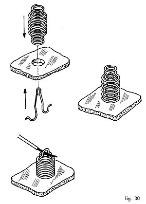
The above mentioned methot is without using solder. When I started on electronics the prototyping boards were very expensive so this was the first method I used, got a little bit of wood, made some holes, bought a coil spring, cute the spring in small elements and placed them on the holes in the wood base. I just didn't used the clamp like this method uses because you just need to bend the spring, put the component lead between the spirals and leave the spring return to it's shape. It's a nice method if you don't have any other way of doing it. The sprimg must be an extension type spring and not a compression type like the above methot uses.
The second method that I allready used, is with small metal thumbtack's placed on a wooden base, you just have to solder the components in them. A photo of one "crystal" radio I made some time ago (the variable capacitor allready went to another project..):

I was thinking if I should bring again the subject on Navtex.... but I will spare you my frustration on this subject. Due to several constraints I normally only have time to make tests on one of the daily navtex transmissions.... that gives me a window of 10 minutes to test the receiver and in some days there's a lot of static and interference so this will take some time until I post a complet working schematic of the receiver. My last experiment was with the divide by "n" circuit (http://speakyssb.blogspot.com/2010/03/divide-by-n.html) connected to an NE602... saw some signals but very burried in noise.
Here the photo of another atempt with the 416Khz vfo wich is not stable enough to leave unatended.


2 comments:
Hi Ricardo.
Back in the 1960s you could buy an Electronic Engineer kit made by Philips which used this form of construction. It included a wooden board with a grid of holes, and cardboard overlays punched with holes and printed with the component placement. You could make many circuits such as a morse oscillator, light detector, simple radios. I had one as a kid - it was my first direct experience of electronics. I wonder how many others remember them?
Hello Julian,
PA2OHH in his site (http://www.qsl.net/pa2ohh) has a reference to the Philips EE8-EE20 kit.
My "homebrew" kit was built in the mid 80's and it was a similar copy of the boards we used at school to learn electronics, probably they were copies of the Philips kit...
Post a Comment