Tuesday, April 27, 2010

Internal impedance measuring

Decided to measure internal resistance on the Si570 kit. It's a somewhat impossible mission without proper test equipment, eg: an oscilloscope or similar.
One way somewhat acceptable of measuring the impedance is... to place another impedance and measure the voltage drop. If it drops to half the open voltage then the impedance is the same of the one placed in the circuit. That's a simple ohms law (voltage divider)

Now, you don't need to put an exact value impedance...because you don't know the internal impedance.... in the books an carbon resistor has the same impedance of it's resistance.... in real live if you don't go far on the frequency it's almost the same.

So....measure the rf voltage of your oscilator in open circuit, that will give you "Vosc" then place an resistor on the ouput and measure the rf voltage on that resistor, will give you "Vtest".

The formula for the internal impedance is one of this:

Rinternal = Rtest * ((Vopen/Vtest) -1)

or

Rinternal = Rtest * ((Vopen - Vtest)/Vtest)

You can assume R = Z for resistive circuits.

The formulae are equal just one mathematical pass more on the first one.

or if you are lazy then go to this online app to make some calculation:
http://www.sengpielaudio.com/calculator-InputOutputImpedance.htm

Now my results: 7 Ohm, 16 Ohm and.... -10 Ohm with 3 diferent Rtest resistors....will have to check again my procedure because something is wrong, I should never had a negative inpedance. The diference in 7 and 16 Ohm can be traced to resistor tolerance and measuring error.
Life is not linear!

Friday, April 23, 2010

A box for the Si570 kitt


Decided to put the second Si570 kit in a box, here's the outcome.
The box aluminum was very thin and I didn't placed a protection in when driling so got some marks, nothing that a nice front plate won't disguise.


Doing some house clean up, found 2 multimeter. My first ever multimeter (my father ofering circa 1988) and a digital one, placed a new battery on the digital one and it works. My first one never worked very well in AC voltage range, it went two times for repair under warranty and never returned ok. Incidentally my broken scope is of the same brand. So, just in case, don't ever buy "Kiotto" brand equipment (I think it's some rebranding for local market)

Tuesday, April 20, 2010

Over 12K visitors


Since I placed statistics online there were already over 12K visitors to this blog, I only hope that means 12K new projects for those who visited this site.

I try to keep the blog on the democratic side...well not exactly democratic because I am the only one who writes and review the comments (there are many spammers around) but I am open to suggestions on how to improve this blog. Maybe more technical subjects, more general news, more nude girls? Leave a comment or send me an email on your ideas.
I am not a native English speaker so I always try my best writing but I am open to suggestions on how to improve communication.

Now let's see the top 10 visitors and the less frequent:

United States - Where the biggest ham radio population lives, so it's logic
United Kingdom - Probably the second bigest ham population
Portugal - This is me reading this fine blog :)
Italy - I wasn't expecting, since I have no 5KW amp project in the blog...:)
Indonesia - Had no idea there were so many hams there.
Germany - Lot of hams there, from what I could see when I went to Friedrichshaffen
Brazil - Os nossos irmãos do hemisfério Sul
Romania - Not expected
France - Oui, ça va bien?
Netherlands - I exchanged some emails with Dutch ham's so they probably see the blog...

Now the less frequent ones...but also important.

Guatemala
Senegal
Netherlands Antilles
Andorra
Maldives - wan't to exchange QTH?
Albania
Armenia
Saint Lucia
Tunisia
Mongolia

Thank you all for stopping by.

Ricardo, CT2GQV

Sunday, April 18, 2010

World Amateur Radio Day - April 18

...Today, case you didn't noticed is the world amateur radio day, the date matches the foundation of IARU.

"...Created in Paris, France, the International Amateur Radio Union has been the watchdog and spokesman for the world Amateur Radio community since 1925. The IARU Constitution, last amended in 1989, organizes the Union into three Regional Organizations that correspond to the three radio regions of the International Telecommunication Union (ITU). The IARU Constitution also provides for an IARU Member Society to serve as the Union's International Secretariat...."

Source: http://www.iaru.org

Member societies at: http://www.iaru.org/iaru-soc.html

Some member societies:

REP (Portugal) - Founded 1926
ARRL (USA) - Founded 1914
RSGB (UK) - Founded 1913

73 de Ricardo - CT2GQV

Saturday, April 17, 2010

USB SW receiver Si570 based

...that's Uper Side Band and not Universal Serial Bus


Some time ago I started assembly of a future SW receiver based on a 10Mhz IF (there was a 10Mhz crystal promotion at the local electronics shop so I bought 10 for 1 Eur, I think). The idea was also to have some modules in a pcb for making some tests.
Since my second Si570 kit is already working I decided to use it as vfo.

Schematic is not complete (part module diagram, part schematic) but you can see them in some receiver schematics around the net:


DBM is from here: http://www.qrp.pops.net/images/2008/2008-larger/big_dbm.gif
and was made without matching the diodes (1N4148) and with diferent wire sizes in both coils...

Crystal filter and if preamplifier is from Bitx: http://www.phonestack.com/farhan/bitx.gif (see Q3 and the crystal filter) The crystals were match at no more than 80Hz difference from a reference value.

NE602 is...well...is an NE602 runing with an external oscillator.

The antenna used in this quick test was the Mini-whip with the antenna spliter (see the schematic somewere in this blog), nice signals were coming in considering there's no bandpass filter before the DBM.

Video is on 20m band with some French hams chatting. So I guess at least 1200Km range from here (didn't checked callsigns). I was also listening to Shannon volmet station and that acounts for at leat 2000Km. Not bad for some components in a PCB and a piece of cooper as antenna.


Thursday, April 15, 2010

UHF Yagi Uda antenna

Addendum, here's the complete antenna (overstatement)...built in 30' with coat hanger wire.
Does it work? Look's so but no QSO so far with Arecibo radio telescope...

Heading to the moon...
Soon as I heard the some crazy guys (KP4AO) are going to frie the moon via EME (http://dxinfo.ea3bhk.com/Special-events/KP4AO-Arecibo-Observatory-Amateur-Radio-Club-on-432-EME.html) I had to do something, at least for some reception.
I like making antennas so here is the oportunity to make one and probably operate something (don't expect that 5w will be enough but since they have big ears we never know) since I never operated SSB on 70cm band... I hope both my capable radios are still working :)

Here's my drawing:


Driver element is feed "live" on the lower side and "ground" on upper side (in the drawing)
and made in #10 copper wire... whatever that means :)... I will get the first wire that look's easy to work and has some style... which is very importan in antenna design

Elements are made of 1/8" diameter which is 0.31cm (3.1mm)

Boom will be made of wooden.

Antenna is made to operate at 432Mhz.... don't try at 20m

Made conversion from "inches" to "cm" based on 2.54cm/Inch, enough accuracy for me.

Original design from here: http://www.wa5vjb.com/yagi-pdf/cheapyagi.pdf

Here's the same design in html format:
http://www.fredspinner.com/W0FMS/CheapYagi/vjbcy.html

Here's another with dimensions rounded from the original article and some construction details: http://personal.inet.fi/koti/olavi.vahamaki/LowCost_432MHz_Yagi.jpg

There's small diferences in sizes... I based my design in original article.

Testing was not done yet...use at your own risk

The Si570 kit is working!

Thank's to Kees (K5BCQ) help, now the kit is working!

After all it was one of the most common "rf" issues.... power supply coupling. A simple parallel 2.2uF capacitor in the power supply sorted this one out. How can one figure this one out since the problem only happens when addressing memory from 0 to 7.... or going greater than 20Mhz...? Amazing!
Now it's time to put termination on the Si570, boxeit up and make some sort of fantastic radio around this nice litle vfo....


Tested the low end on this particular si570 CMOS and it can go as low as 4Mhz, that is 1Mhz for some types of SDR's. I'm going heterodyne anyhow... bellow 4Mhz will go with an upconverter.

Tuesday, April 13, 2010

Cool boxes for homebrew projects

I placed receivers/transmiters on computer power supply boxes, Sardine an Tuna can boxes, plastic bottles, wooden boxes but never tested on a toaster or lunch box... If the receiver doesn't work or solar activity is low you can always make a nice toast! Found this while "surfing" for relaxing from my homebrew problems (see the end of this article)...


From OH6DC "Toaster tranceiver" at: http://sites.google.com/site/oh6dccw/toastertransceiver

Now for the lunch box (I really like this one..)


Original article at: http://sites.google.com/site/oh6dccw/picnictransceiver

Give a look at the stange cw keys collection (their really strange)... http://sites.google.com/site/oh6dccw/strangecwkeys


This post was supposed to be on the Si570 but after assembly of the kit (see last post) I saw that it is not working 100%. I am "debugging" with the help of Kees (the kit maker) to find the issue with it, everything looks normal but I am having some reset's addressing some memories. I hope I don't have to send the kit for repair, last one it was my fault (very stupid) and I am sure this one is also too! So I want to spare myself the shame... :)

Sunday, April 11, 2010

Si570 kit - new one

I had this Si570 kit for some time and decided to assemble it...Personally I'm not a big fan of smd devices but had no other choice in this case...

Some stages of the assembly


When I switched it for the first time I had some wrong indication on the display...something like "8.8. 0", tough that something was wrong, checked all the soldering s and...again the same problem.... RTFM and "voilla"... you have to initialize the kit.... after all it was working at first time, remember to read first and solder latter.


This is an excellent kit for a vfo or generall coverage transmitter/receiver (I'm using one in an airband receiver) but the instruction are not the easier to follow so if you want to assemble one I sugest reading the following link:

http://www.cliftonlaboratories.com/si570_kit_from_k5bcq.htm

There's a nice tutorial there... withou it I was proably still reading the schematic righ now...

You can get one kit from here: http://www.qsl.net/k5bcq/Kits/Kits.html

Weather is getting warmer in this side of the world so instead of heading to the shack I might head to the beach.


The outside temperature sensor is bellow the roof tiles...

Wednesday, April 07, 2010

PTO mechanics

The hard part on a making a PTO is the mechanical part so I took some minutes to think about it and started doing one, hopefully it will be somehow stable...
Not much description here, there's an old ball bearing in the shaft and some peaces of aluminum to remove the play. There are 3 nuts to remove (not very successfully) the lateral oscillation/play.


If you have a nice tool shop then please have a look at this one: http://www.qsl.net/g3oou/pto.html

If you are a null working with tools then this one is for you: http://www.wa6otp.com/pto.htm I only wonder what is the sensibility to hand capacity...have to try one...

I would say mine is in bettwen...

still and very important is to place the coil and the moving core....

The moving video, I didn't applied grease yet, ence the noise... just to clear things out...:


This PTO was supposed to be placed in a receiver I am building but the PTO board is bigger so I will use another VFO.
Look at the size of the pre filter if amplifier.... it was a pain to build, the schematic is from BitX (the amplifier I mean), the rest is a mix and is not yet complete.

Saturday, April 03, 2010

Electronics prototype method

Recently I came across a site (http://www.qsl.net/pa2ohh/oldproj.htm) with some ideas on rapid electronics prototyping.


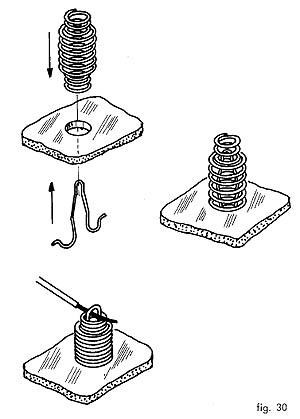
The above mentioned methot is without using solder. When I started on electronics the prototyping boards were very expensive so this was the first method I used, got a little bit of wood, made some holes, bought a coil spring, cute the spring in small elements and placed them on the holes in the wood base. I just didn't used the clamp like this method uses because you just need to bend the spring, put the component lead between the spirals and leave the spring return to it's shape. It's a nice method if you don't have any other way of doing it. The sprimg must be an extension type spring and not a compression type like the above methot uses.

The second method that I allready used, is with small metal thumbtack's placed on a wooden base, you just have to solder the components in them. A photo of one "crystal" radio I made some time ago (the variable capacitor allready went to another project..):


I was thinking if I should bring again the subject on Navtex.... but I will spare you my frustration on this subject. Due to several constraints I normally only have time to make tests on one of the daily navtex transmissions.... that gives me a window of 10 minutes to test the receiver and in some days there's a lot of static and interference so this will take some time until I post a complet working schematic of the receiver. My last experiment was with the divide by "n" circuit (http://speakyssb.blogspot.com/2010/03/divide-by-n.html) connected to an NE602... saw some signals but very burried in noise.
Here the photo of another atempt with the 416Khz vfo wich is not stable enough to leave unatended.


Friday, April 02, 2010

High performance bi-directional mixer / Fooled

Have you been fooled by the last post? No? Ah, you were paying attention to the schematic! Did you order the components? Bad luck... their useful anyhow...
It doesn't work... I think. Just some components placed in paper... It was my April fool! Have a nice day!

Thursday, April 01, 2010

High performance bi-directional mixer

Following some ideas from a fellow ham decided to try an high performance rf front end with easily to find components.
This particular front end is excellent from around 1Mhz to 200Mhz with the added advantage that is bi directional and you can use the same schematic for the BFO part but it's a waist of ferrite cores so use the lower part of the schematic the LM741.


In my preliminary tests this front end had the same performance of my FT-102 and I wasn't using bandpass filters... When the TS-50 was crumbling with BCI this front end was digging out signals from mars... I guess the secret of this design is dividing the signal in two and then combining again out in oposit phase. Will investigate this better tomorow.