Following some emails exchanged with CT5JZX about an possible VHF FM transmitter he will build I decide to give a little try on FM tx... My last attempt was about probably 20 years ago when I built an broadcast band transmitter enough to give music to all my neighbours.
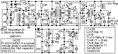
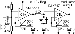
This was just the IF part of a possible transmiter I will build one of this days... FM modulation is via 2 1N4001 diodes working as varicaps, mic preamp is an LM741, the mic is the one from last post here on the blog. Since I didn't have any 10.7 Mhz IF transformer for the coil I brew one just for testing with 20 turns on a red core (no calculation, I just figure it would be around 20 turns, came out as 10.9Mhz, nice). I tryed an 10.7Mhz cristal but without success using 1N4001 as varicap, also tried an 10.7 ceramic filter as oscilator with limited sucess, probably in the future will try again with a cristal for stabilty porpose. The original design is with an coil.
The output of the oscilator connects to a capacitor and then to the frequency counter, the ferrite coil on the righ is the pick up coil inserted on that capacitor and connected to the antenna input, enough to give S9+Full scale on my receiver..... problem is it must be well filtered because there's a lot of harmonic energy at the second harmonic....

Eventually a schematic will be post here as soon as I draw it, basicaly is a design by Harry SM0VPO with only minor component changes. In the video I didn't adjusted the deviation and level pot and didn't let the oscillator warm up a litle, with the right coil I think it will be quite stable, suficient to make a transmiter.
Another project that will have to wait a itle bit.
Here the first test, I was receiving a litle bit out of the oscilator frequency:
Schematic is part of this (only made fron the left of the circuit to the first BC547 transistor, the oscilator, and the 1n cap were I connected the freq. counter). Power supply is 9v, didn't know what the value of the zener was, probabli 6.8v, but works ok with 9v, removed the 12k fron the schematic.

Modulation from this:

Didn't had the 747 so used 2 LM741 (one LM and one uA), one of the 50K pot was done with an 100K parale with an 100K resistor. Didn't had at the moment 47K resistors so used 56K for the voltage divider in the first opamp. Power supply used is again 9v.
Original work is from: http://www.sm0vpo.com/
2 comments:
SM0VPO is named Harry or Harold. :-)
73 de SA5BKE
Eric,
Thank you for the information. My typo mistake! Corrected. At least someone reads the text :)
73 de Ricardo - CT2GQV
Post a Comment