The "Bitx" is a simple transceiver designed by Ashhar Farhan, VU2ESE, with extensive use of commonly found and inexpensive electronic components. It's a simple single band SSB (nothing is simple at rf) design with extensive use of bidirectional amps.
One of this day I was thinking (I do that sometimes) that could be nice to add some FM capability (RX/TX) for the Bitx or, for that mater, to any other similar design. For the RX part, there are plenty of FM demodulator IC's and even some old school designs using IF coils, but keeping the tradition of doing more with less or at least with more available parts around the world, here's one of my tests.
Transmitter part:
Audio modulator (I used 2 741):
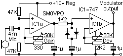
Implementation (I added one mic amp):
The design is by SM0VPO except the mic preamp that is a common preamp circuit
Now for the FM modulation, a super VXO at 10Mhz, bellow:
I used a previous pcb board from the AM light modulator for the buffer power vxo supply (AM for the bitx? Maybe next!). Hard to get parts? probably the BB105 varicap diode but I'm doing some tests with high power zeners (1 and 5W) that probably can be used.
Receiving:
The demodulation part:
The schematic in the receiving part, was an adaptation from a "Russian" schematic I found somewhere, so components values were more or less my interpretation.
The amp before is the same of the one after the crystal filter in the Bitx design..
Honestly schematic looks like a phase demodulator but I still didn't fully understand it, looks more a full wave AM demodulator than an FM one. Fact is, it works to some extend.
The reception part is to be fitted after the crystal filter in the Bitx, of course a new wider filter design have to be used due to FM bandwidth.
The above schematic do works but will need more amplification (another IF amp probably) or at least more impedance match in the reception part, so it's not in for "production level" and I will not put here full schematic. Consider this a starting place for some experimenting.
If you have any simple design for FM demodulation at 10Mhz I would like to know.
Anyhow FM only makes sense for a 10m version of the Bitx or for transverter use.
Have fun!
Homebrew of radio equipment, antennas, tuner, etc.
Wednesday, January 25, 2012
Tuesday, January 17, 2012
Ciencia an Mirandes - Al Centificu Eilustradu
Or: "Science in Mirandês - The illustrated scientific"
This post is not only about ham radio or electronic design but about an interesting blog I found; not only for the subject in it but because it's written in a language I know very little.... "Mirandês".
This is the first blog I found about ham radio and science in this language, and I found it by mere chance during a web search.
You probably don't know (for the not Portuguese natives, and many natives for that matter) much about this language but Portugal has two official languages (since 1997), yes that's right, beside Portuguese there's also "Mirandês" language.
Mirandês is just spoken by a very small community in the North East part of the country and it's only learn at school in that area, for me and as a simple explanation it's a mix of Portuguese with Spanish adding the country North-East accent. For a language student that could not be the most accurate way of putting things....for English readers to understand I would say it could be a mix of ancient English with current English on a Scotish accent :)
Here's a litle sentence from the blog, in Mirandês and my translation to Portuguese, Spanish and English so you can see similaritires between languages.
In "Mirandês":
"De restu hai uns méźes atras la NASA dixu que punarie outra véç l purgrama an lliña... y ya sta"
In "Portuguese":
"De resto hà uns meses atras a NASA disse que punha outra vez o programa em linha...e já está"
In Spanish:"Además hace unos meses, dijo la NASA volvió a poner el programa en línea ... y ya está"
In English:
"After all, some month's ago, NASA said that would put again the program back on line (track)... and it's done"
I point the fact that language knowledge is an valuable tool, normally my radio searches are in English because of the language wide spread but I do find many interesting pages on other languages like French, Dutch, German, Russian and Japanese, being, from my perspective, the last two the most outside the norm radio designs (specially in component references). So, next time, you, the reader, could try to search something translated to another language, you'll see some different results for sure!
The "ciencia an mirandes" (Science in Mirandês) blog is here
Even if you don't understand the language at least the images and videos are universal.
Have fun, in any language!
Friday, January 13, 2012
Handycam CCD-F370E mini crt - II
I have a spot!
...but before this image, first I cut the vertical deflection coil... had 50% chances of finding it on the first try... I did!
Then cut the horizontal deflection coil (actually I removed the plug on the coils) and got the spot! I new beforehand that the timing/blanking circuit would work erroneous or would stop working since the coil is part of the circuit so I replaced the crt coil in the control circuit with a 33uH or 330uH choke coil (I think... orange, orange, some sort of grey, have to measure and try another), the spot got better and more focused but still not perfect.
..I could just had hook up some signal to the coils...but no! This way is more fun!
Now the problem will be the "Z" axis, I can build an video blanking circuit in tandem with a sawtooth generator (and feed the video in the original circuit) but that would be to much trouble, I will try to control directly the crt or add just a marginal circuit in the blanking part which is pin 11 in the following control circuit.
More search (use an translator if your Russian is like mine...zero, besides: Vodka, Polyakov, Piskunov and Dasvidania! Sorry for the spelling) and I found a similar design (from Samsung) on the one I have:
The red dots are the blanking circuit, I am thinking in "attack" directly "G1" on the tube or maybe the center part of the pot controlling the intensity, (not perfect but should work), I think it's better than removing the tube and make a new HV circuit.
have fun, I am having... a lot!
Thursday, January 12, 2012
Handycam CCD-F370E mini crt
Short story: I have a Sony videocam bough some years ago but I think I never recorded anything with it, it was bought second hand and for some years it worked, I mean, I could see the lens image on the viewfinder but it stopped working some months ago, the camera can't focus anymore and I have only what looks like out of sync in the viewfinder, probably some cap leaked and or out of specs.
Since I never used the camera and there are less bulkier and digital alternatives nowadays, why not open it up and remove some components; being the most interesting parts the microphone, the lens and the view finder. Specially the viewfinder looks interesting to make a tiny oscilloscope (while I don't fix my broken scope) or an ATV video monitor.
Now on to dis assembly:
The viewfinder part...
After searching I found some people in the same path but no detail on pin out for the minicrt, so, on to some reverse engineering.
It took me some 10 minutes to find the connection pinout, just to discover the crt would not give image although the record led (connected to the crt control board) indicated power. I increased the voltage to test on 9V (was using 6V and is correct). Nothing! Bloody hell! I hate reverse engineering!
Stopped and waited some time, then returned and had another look just to discover my fault, I was biasing the power the wrong side, I mean I thought the led was switched by the positive but instead is the negative (cathode, anode is always connected to +), it also helped tracing a big coupling cap connect to the only IC in the board (it had to have power directly connected so easy to trace to power line)..... "et voilá", the thing works but I still didn't connected any signal to the board.
The small component near the crt in the following image is an 1W zener.... it's really small the crt but with the lens it's easy to view.
Now the pinout:
After all this work.... if I had just looked bellow one cap I had noticed that there was an video IC bellow it.... if I looked on the IC datasheet I had easily found the pinout, live and learn! Now I have to trace deflection coils to the AN2512 ("Electronic View-finder driving IC") to make tests on deflection.
Now the lousy video:
Have fun!
Monday, January 09, 2012
The "Speaky" reborn
The Speaky HF SSB/CW transceiver kit was the main reason for this blog to start, at that time I wanted to document the building process of the kit but after a while it became the virtual space for my radio electronics projects.
I did finished the build process of the kit but got some bug's on the first test so decided to stop for a while. Now I will rebuild the kit, mainly the cabling to the main board, I made it short the first time and got to the conclusion I need easy access to make further tests.
Today I started debugging the project, the first problem was the frequency counter, a swapped cable (signal and ground) was the reason for not counting the LO frequency, now it's ok but there are around 30 new cables to be done.... lot's of work for the upcoming times....
Only the 40m band module in place, still need to solder the 17m one and probably add another one, the main board allows for 5 band modules, only ordered 2 at that time.
It was also an opportunity to clean the mess in the bench :)
Saturday, January 07, 2012
LASER AM modulator
Here's the LASER pointer AM modulator, QRO version, as promised in last post!
The receiver used in tests is the same I've been using in previous tests except I changed the 2 green LED's for an IR diode.
If the LASER is pointed directly at short distance directly to the diode the receiver (LM386) get's overloaded, just point slight off-side.
I'll stop for now this light comunication tests, was just to test the concept. I also tested the AM modulator circuit against a small crystal oscillator buffer and it worked nice.
Have fun!
Subscribe to:
Posts (Atom)