Friday, March 30, 2012

2m FM TX

Here's a duplication of LY3H design with my usual variation...eg...replacement of some components by lack of them in the local electronics shop.

The original schematic:


Here's the outcome:


I didn't had BFR93 transistors so replaced by BFR91 and the BFG591 was replaced by an 2N3535. RC4558 is basically a double LM741, so I used the LM741. The tunable coil was replaced by a red core toroid with around 30 turns and frequency is set by mean of a 25pf trim capacitor.
The critical part are the first tuned circuits at 72.5Mhz, nothing a good dip meter doesn't handle, I had to remove one turn on L2 and L4 to put on frequency. Also with the direct replacement for the 2N3553 I am only getting around 0.6W, probably with some tuning 1 W could easily possible.

Since the frequency control crystal has a glass envelope why not put a LED behind to make it glow....looks like a magic eye tube. I used a double color LED, so green color when in rx and green mixed with red on tx...


The box came from an old CD-ROM drive.

I am now in the process of adding a tone encoder (top right board on the box) and a different mic (dynamic) so those results will be posted as soon as I finish it.

I'm very happy with the design and probably will be the shack main rig for repeater access.

Thank you LY3H for the design an help.

Have fun!

Thursday, March 22, 2012

Next project

No it's not a copy of HAL9000....(but i've had a Linux machine named that way!)

During build process...More details when's fully operational....

Now... what shall I do with 4 modules like the one bellow...
They reached the end of life in a nearby garden but still operational....

Monday, March 12, 2012

FM for the Bitx ? II

More ideas on easy and cheap FM add on (RX) for the BITX transceiver...

With an TA7303 and a 10Mhz crystal between pin 6 and 7 ?...
The original idea uses an ceramic element...

The cheapest TA7303 I could find costs 1.03 Eur...

And a circuit similar to one I've tested on another post:


The above one is a little bit more tunable and probably uses more easy to find components...without a limiter in front you probably "get" AM as a bonus!

I have to test...

Have a nice week... this was my weekend:

Wednesday, March 07, 2012

Low budget radio

Here for the low budget lovers....

Just having fun with the VFO on a "pound-shop" radio....

The new 500Khz band:


NOAA sat maybe?

It can go to 144Mhz... an a small transmission in the airband was heard...

Wednesday, February 29, 2012

Regen receiver audio and UHF oscillator

Here's a small video of the ARRL simple regen receiver working, for posterity...


Note the "Swiss army" tuning shaft on the trimmer cap... as we say: "those without a dog hunt with a cat.."...

I think it's not this time the regen will get a new box, I already started cannibalizing one of the boards to make some tests on UHF, maybe an UHF receive converter will come out of this...

The result:
The circuit:

..another nice photo...

The circuit came from LY3LP 70 cm rx, I just used the T3 oscillator part.

Here's what I had of drift after 1m warmup with the circuit just bellow a reading lamp:


Considering the runing frequency I think it's not bad... the idea is to feed this LO (290Mhz) to an ADE-1 mixer down-converting 440Mhz to an 156Mhz VHF FM module I have (it's in the photo bellow the frequency counter) and didn't managed to program it in another frequency. An PLL stabilizer is then also needed.

I noticed that for a frequency bigger than 490Mhz I had to short-circuit C32 for the circuit to oscillate. I used an BB105 varicap and BFR91 transistor instead of the components in the original schematic, for L6 in the "final" prototype I used an ferrite bead (around 3mm long with 1mm hole and the wire passing inside one time only) recovered from a computer motherboard (good source for beads), R17 used 56 Ohm instead of the 33 one. Not critical I guess!

Have fun, generate some signals!

Friday, February 24, 2012

Simple regen receivers

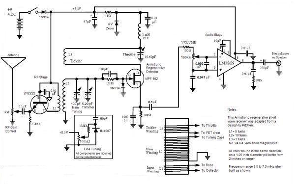
Some years ago I built the ARRL simple regen receiver, in fact it was my first working receiver. I never placed it in a box and the board as been cannibalized when components short. This time decided to rebuild the receiver again and hopefully place it in a nice box. My original construction was on a PCB but now decided to place it in wood substrate.

The schematic:

Here's the preliminary tests with the transistor amp and not the original LM386 in the design:
This method of building is nice when you don't have PCB around, not the case but gives some old style to the build.
And the link to the original article.


While building (or rebuilding) the ARRL design, found another simple regen receiver on g3xbm site and decided to give it a try....

I built the g3xbm schematic on "Hertz" day, and guess what.... it didn't oscillated! Yesterday I figure it out, probably a broken FET, I replaced the part I had by an BF244 (an MPF102 on the original design) and started working, except when my crystal headphone was connected, after all it wasn't a crystal headphone but a simple headphone in a look a like crystal phone box.
The one on the photo is a true crystal phone one and is from my dip meter accessories.


Both set's do receive but as they are simple designs so you should not expect big performance. I intend to build the following design in the next few days, looks a little more promising. You should read some considerations on regen's on the link above if you're interested in building this type of receiver....

Have fun!

Wednesday, February 22, 2012