Sunday, December 31, 2017

Egg beater fix

Friday afternoon....going to prepare dinner, egg beater is needed.... it works first time and then stops...no bang.... after a days work troubleshooting I don't need more of it :)

There are only 3 possible faults for a mains powered device:

1 - No power
2 - Open circuit
3 - Short circuit

There was power and there was no short circuit, leaving the open circuit possibility, in fact it was immediately confirmed since no resistance was measured from the power terminals... I only hoped it had not been a short on the engine windings causing the open circuit.

I confess that opening was easier than closing in the end, mainly due to mechanical interlock of the eject mechanism.


Here's the fault....

..on the speed/on/off switch, since it rotates (the transparent plastic part, along with the center washer) the wire broke at the terminal (mechanical stress).
In the picture was already in place for soldering, should last another year or two.


And pictures in the process of finding it:


 ... Sabichi brand...at least the electric motor looks reasonably built.

Just looked their website (https://www.sabichi.co.uk/the-company), that's not bad since most brands are just a sticker:

 ".....with one mission – to bring fantastic quality homewares to our consumers in the UK at a great price. We haven’t looked back since...."

.....Marketing.... it just means: bring Chinesiun or Eurocrap lower grade devices, re-brand and sell for the highest possible price...
Anyhow, even in our hobby we are seeing the same...


Have a great 2018!


Friday, December 29, 2017

Bench power supply ( part I )

This is part I from the build of a small bench power supply.
It's going to be 3 supplies in 1, one from 3-19V (build bellow), a 5v USB output and a variable dual rail implementation of the LM317/337.
The first one, already finish, is using an LM723 implementation, nothing special, just picked the first schematic that seamed viable and built it.
This power supply it's just to avoid having to resort to the 13.8V one from the radio since it will be used for small circuits testing.

Here's the outcome (left size finished minus buttons and voltage display, latter on that):

The USB out (in the midle) it's going to be useful for testing Arduino projects without fear of frying the USB port on the computer, it's just a garden implementation of the LM7805 with two 100nF caps on the input and output.

The schematic that I used for the variable supply was the one bellow (from here):

I used a TIP3055 and TIP31 instead since I didn't had the specified ones, the 600 Ohm resistor was replaced with a 680 one.

Bellow a similar schematic with more comprehensive details of the current and voltage controls (from here):

Inside stays like this:
More details with the TIP3055 heathsink (piece of metal) in place:
and the view to the front panel back side:
The box used was one on sale on the local electronics shop and even include a transformer inside, the only downsize was that you had to build your own front panel, nothing some PCB and elbow grease would not sort out:

Not perfect but works. Bellow another picture during front panel build:
The switch most to the left enables or disables the output, handy if you see something smoking while testing and it cuts faster than the main power switch due to charge on the filtering capacitors.

Enjoy the weekend and see you probably next year!


Saturday, December 23, 2017

OS-5020, Kiotto, LG, EZ, Oscilloscope - Info and placeholder

I have a broken Kiotto OS-5020 to fix, that was my first oscilloscope,  suspect the problem is on the power supply. Making here a placeholder for information related to this scope while I don't have the opportunity to fix it (it's in Portugal).

In the past I tried to reach the local distributor in regards to get the schematic or additional info but got no reply for the two email's sent... so on the good Portuguese tradition.. have a finger and don't count with me to get any more equipment from your business.

I already did before some troubleshooting to suspect the power supply even without schematic but to no success at that time.

This scope comes with many different brand names, here's some examples from the web:

Kiotto (local Portuguese re-branding by "Niposon" distributor):

Goldstar:

EZ


The schematics:

- https://www.scribd.com/document/134639836/LG-OS-5020G-Oscilloscope-Service-Manual

- http://www.testequipmentdepot.com/ezdigital/pdf/os5020-5020c_manu.pdf

Here some good description also with schematic in multiple pdf's:

http://timhatch.com/projects/os-5020g/


Another slightly different unit (9020) but I suspect very a similar schematic:

- http://bee.mif.pg.gda.pl/ciasteczkowypotwor/Goldstar/OS-9020P.pdf


And the OS-9020 version with similar symptoms but same resolution:

- http://charliexray.blogspot.ie/2010/07/osciloscopio-goldstar-os-9020p.html

 The "common" problem with the unit looks like on the negative rail power due to a resistor/fuse, that causes a smaller horizontal trace and no vertical deflection.
In my case I eared a small "bang" when the issue occurred, at power on of the unit, but never found any damaged component on a first glance.

Bellow some posts with matching images (from the post) on troubleshooting of the power unit.

https://www.electronicspoint.com/threads/repair-help-on-lg-os-5020c-oscilloscope.276494/

https://www.electronicspoint.com/threads/connected-my-oscilloscope-up-backwards.268276/

Exactly the same power supply as mine (as far as I remember since last time I touch it, was 5 years ago):


Voltages on the main board:


As soon as I have the opportunity/time will continue the repair on my unit and update here.


Wednesday, December 20, 2017

MAX6675 termocouple reading

Got this little chip already assembled as a module and with a type K thermocouple included, idea is for some other project and/or soldering iron temperature meter.

Initial testing showed max temperature of my iron tip in the rounds of 180C, it takes also a little to overcome thermal inertia and I guess needs calibration since the melting point  of 60/40 solder (used) is 188C and probe was showing 181.
Other methods of calibration could include freezing and boiling water.

Here's the prototype:


Reading the soldering iron temperature (not exactly a scientific grade measurement):


The code used (changed from the library example)  with output on serial port:
--------
#include
// this library is public domain. enjoy!
// www.ladyada.net/learn/sensors/thermocouple
//name=MAX6675 library
//version=1.0.0
//author=Adafruit
//maintainer=Adafruit
//sentence=Arduino library for interfacing with MAX6675 thermocouple amplifier
//paragraph=Arduino library for interfacing with MAX6675 thermocouple amplifier
//category=Sensors
//url=https://github.com/adafruit/MAX6675-library

#include


int thermoDO = 4;
int thermoCS = 5;
int thermoCLK = 6;

MAX6675 thermocouple(thermoCLK, thermoCS, thermoDO);


void setup() {
  Serial.begin(9600);
  delay(500);
}

void loop() {
  Serial.println(thermocouple.readCelsius());
  delay(1000);
}

---------


I also measured using the built in sensor/thermocouple on a JBC type C245 tip showing different values from the K thermocouple included with the MAX6675 module (also not a good idea to use simple wires from the probe to the chip).

 Here's measuring the solder melting point (or higher than that, due to thermal inertia)

Check the size difference between the Maplin "garden variety" type soldering iron and the C245 from JBC. Bellow also an example on how small the JBC tip is:

...and no, I didn't bought the full station, just one tip to "play" around. Looks nice but hard to justify the price and I guess the tip's won't last as long as regular heating element's.

Connection to the Arduino (I used the "nano") from the MAX6675 module is as follow:

DO = pin Digial 4 (D4)
CS = pin Digital 5 (D5)
CLK = pin Digital 6 (D6)

Interesting the module I got has the wrong polarity for the thermocouple printed on the board, that is; one side of PCB shows "+" the oposit side shows "-", If you connect wrongly the thermocouple, the temperature output from the code will show decreasing when it's getting warm and also near freezing point at room temperature (assuming you are not in the north pole doing experiments.....)


Have a great season.


Monday, November 20, 2017

H.A.N.D.


OK, this blog is mostly building projects but sometimes I like to share other stuff.


Got this inside an order of ceramic variable capacitors (10-60pF), from a seller in Bulgaria. This is the second time I buy from the same vendor and if I remember in 2014 I also got something other than the normal goods inside, always a nice touch!

Have a nice day!

Sunday, November 19, 2017

Raspberry Pi in a new box

Some times I just want things done, on some other occasions I prefer to do it correctly...or at least I try!
 That was what happened to the previous box for my Raspberry Pi, just needed some cover so devised this cheap box:


Now it's time to improve a little bit and place it on a more definite location, this was what I come up to (still going to include a front switch to disable video and power to the small display):


Inside: the Pi with it's power supply (wall unit without terminals) and one to  power the video screen (the transformer, diode rectifier and an LM7812 using as dissipator part of the crystal filter box that I butchered in a previous post.):


Still not sure on the placement of the screen since it would go nice on the front panel, problem is; being a little higher than the box.

The back panel where the magic happens:

Pi Ethernet port, USB ports, video and power out for the screen, power switch and mains entrance. Might include later on the front panel a shutdown button.

The plan for this Raspberry is to have it permanently connect to an SDR dongle doing reception work and then access it via another computer.

Have fun!

Arduino Speaks and Talks

Have an idea for a small Arduino meter and would be good to have the output to audio in addition to a normal display. Specially handy for troubleshooting without constantly looking at the meter. Googling on the various options, found a small library (Talkie) that does basically it without any external shield or component.

Here's how simple it can be:

Just add power... and connect pin 3 and GND to a speaker. If more power is needed, then place an external amp. Audio quality is good enough for the application. Voice is the classic computer tone but there are examples with other types in the library examples.

 Regarding the library, its at: https://github.com/going-digital/Talkie but I was having problems with compilation on my IDE due to type declaration so got this "fork" version from here: https://github.com/bertrik/Talkie/archive/master.zip that compiled fine.
 
The result with audio at the first try:


Have a nice week!


Sunday, October 15, 2017

XF-9 S42 9Mhz AM filter from the Telrad board.

On previous post I made a simple crystal tester, that was needed because I was short on 9Mhz crystals and thought that a good place to get them would be the AM filter from the Telrad board. It's referenced as XF-9 S42, 3.6KHz at 3db bandwidth with 560 Ohm impedance.

I was right, there are plenty of them now available, either for USB and LSB:


Inside, the PCB supporting the crystals


 The schematics is more or less like this:
 Interesting, the input goes to the middle of a crystal, first time I see it.

 Another view
 Side view
 It was not that easy to open the box
 The input details, see the terminal going to the middle of the crystal
 The cover, underside and top side.
 The matching numbers to be tested:
 The values


It was not easy to open the filter, I used the "sardine can" method, previously had tried to unsolder the bottom but there was to much thermal mass and still not sure if it would possible.


So, now I have 9Mhz  crystals for the BFO of the boards and for other projects, one of them already take place in the S9 signal generator.

Have a nice week!


Saturday, October 14, 2017

Quick crystal tester

Needed a quick crystal tester, could had lash it up in a little piece of pcb but decided to give it a more robust look and leave it a bit more permanent case is needed again.
Circuit is out of ordinary/common ones and probably will not work with all crystals but for the intended ones it worked, if you replicate you might need a small 20pF cap in parallel with collector and emitter of the transistor, mine worked without.

Here's the outcome testing a crystal:


The counter is a pre-build module with VFD display, couldn't managed to take a decent picture of the display even with a better camera, I was not born to be a photographer...

The terminal connected to the battery was a left over from the exploded battery on the previous post, so some cents were saved.


Schematic:
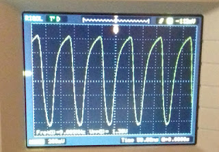
output waveform:


Some more crystals in testing:

And more pictures:


Have a nice weekend!


Sunday, October 08, 2017

The exploding battery!

Nothing built in the this blog post, instead some destruction!

In Ireland it's common to have in all divisions of a house smoke detectors, I think this is by legislation and mostly because there's a lot of wood involved in construction.
In Portugal, for example, that is not common since most of the houses are cement build and not mandatory.

Any how, on the present house I'm living one of the smoke detectors started beeping, that's an indication about battery status, the detectors use standard 9V PP3 battery for power.

I replaced the battery for a new one, checked the old one and since it's was still showing near the normal value keep it to power some electronics.
In this case I used it to power the S9 signal generator that was siting in the edge of the bench as seen on this picture (except in vertical position):


One of this days, while working at the bench eared a loud bang, initially since the FT-707 is on top of his power supply I tough that it had slipped sideways.... further investigation and saw the battery hanging free on the edge besides the S9 generator, OK it could had slipped hit the bench but does not justify the loud bang similar to a hammer hitting a wood bench....

 Here's what happened in pictures:

 imagine the pressure to crack the plastic.
 and force it outside the cover


 yups, the battery had long passed the time it should be running.
 The front post also suffered and was removed and used, as battery clip, for a project since this ones are easy to solder on the inside. The S9 generator uses one clip from another dead battery.

Bellow the elements inside:
There's is noticeable degradation....

Anyhow, destruction without personal damage is always fun!

Have a nice Sunday!