Tuesday, December 30, 2014

Anatomy of the Sailor R104 receiver

From the previous post you know I bought an Sailor branded R104 and a T126 companion transmitter in possible working state...

I had now the chance to test the receiving section, the R104.

It works....at least the channelized part of the receiver, the bands parts it's not working, will have to investigate it. The bands and the channelized part don't share the mixer and part of the front-end so most likely issue is there.

I have to admit that the radio is not exactly built like a tank (internally, as in some military equipment) but is very well thought in some build details, I think the builders main concern was the entrance of salt water in the equipment so although not waterproof it has some rubber parts to seal the most exposed parts and also some oil embedded cotton in the potentiometers shafts. Also the outside enclosure almost bullet prof.

Here some photos:

Speaker "cabinet":

The speaker itself:


The oil embedded cotton seal and front panel rubber seal:

The speaker output plug was broken and some previous owner tried to fix with scotch tape, very bad work, I already bought a matching one to replace and keep the radio the most original possible way (was the last similar phone plug in the shop):


Another previous atempt on fixing the radio, there are ruber seals around the regulator and plugs panel and they were glued to the back pannel only a poor job was done and the ruber seals ended sliping from the orignal possition:


Internally, pre-selector and channelized part:

 Difference oscillator 7.3 - 6.7 Mhz (two crystals on top board) for clarifier, the other boards I think are the IF amp and AGC circuits

USB filter and  bands oscilator


Well... it will be my restoration project every time I return to Portugal for some vacations.

I wish you a happy 2015....and 2016... and so forth!


Tuesday, December 09, 2014

Sailor R104 + T126

I know, did I needed this boat anchor?  Probably not!

Sorry, couldn't resist since this was the only radio I managed to break in operation (many years ago and that's another story)... luckily was only the fuses and that because the antenna cable was corroded...

There's nothing like the first love, so I bough this exemplar relative cheap and in supposed working condition (didn't tested yet). The radio was delivered in Portugal last week and I had no time to power it up, maybe during Christmas week.

It's composed of two main modules, the transmiter T126 and the receiver R104, aditional modules are the power supply, the speaker and the external antenna relay. Only the mic is missing.
 Weight is around 26 Kg, now that's a proper anchor!
There's a metal support that you can use to fix it to a wall and allow the modules to slide in for easy maintenance.

Transmitting part and power supply:
 

Receiver and speaker:


Inside the transmitter:


And the corresponding schematic:
.... that is 6 output TT22 valves for something around 400 W...

Modulation part of the transmitter:

I might in the end just use the transmitter unit for parts, specially the output tubes and the crystal filter.

Schematic and ssb filter characteristics (modulator):

Note the asymmetrical characteristic of the filter:


 ...you probably noticed my blog pictures quality just passed from the normal "crap" to something more acceptable, that's because I have a new camera, unfortunately you have to keep the same photographer...

Have a nice week!


Monday, December 01, 2014

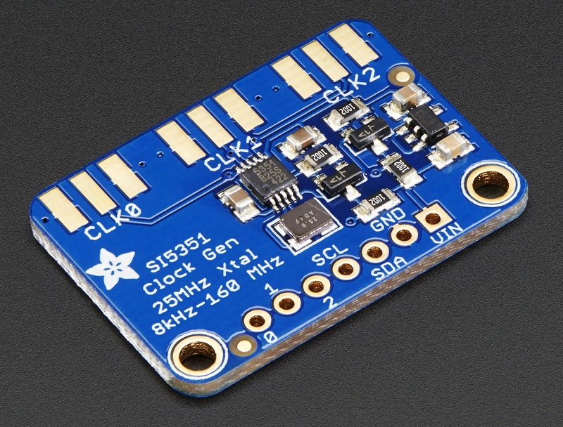
Silicon Labs Si5351A loaded output

I'm really considering this device (Si5351A) to be the VFO and BFO for my new transceiver (Trevo).


I implemented some code, on the Arduino, to change frequency depending on the position of a potentiometer since I'm waiting some rotary encoders to arrive.

While I don't proceed with more code, started to investigate the best way to interface the output to an ADE-1 mixer since I'm using them on the "Trevo".
 Saying that: connected the oscilloscope probe to one of the Si5353 outputs and started measuring:

Unload (or for that mather loaded with the scope probe) I got around +19dbm.... _if_ the voltage was applied on a 50 Ohm load (measured 2 V on the scope).... that looks promising...., let's try loaded... and it drops to the following values and matching load (a carbon resistor was used):

47 Ohm: 316 mV
100 Ohm: 700 mV
220 Ohm: 1V

That sayd then the output impedance is 220 Ohm, not even a calculator is needed...

The stated datasheet impedance, for the Si5351, is 85 Ohm, I might be doing something wrong or not taking in account something else... I might try again with the probe in 10x to raise the scope loaded impedance.

 Anyhow loaded with around 50 Ohm (47) that's still +3 dBm, enough for some more testing ...
 Test frequency was 19.100 Mhz,


Have a nice week!