Sunday, February 24, 2013

Panadapter/bandscope/spectrum analyzer/decoder idea


OZ9AEC had the nice idea of connecting one of those USB TV dongles to a "Beaglebone" board:


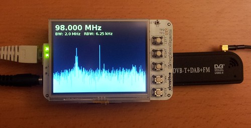
 With that he got an "Spectrum analyzer", for about 140 Eur (more or less depending on supplier), and a computer running Linux.

Now...imagine...connect the same Beagle board (or any other small board running Linux) to a USB sound card, a USB to serial converter and a USB SDR receiver. The SDR input connected to your radio unfiltered IF, the serial interface to the radio control port and the sound card to the radio audio output and you end up with a box similar to this:


..except it will be a little bit cheaper and with more options... the P3 costs about 699.95 USD (530 Eur) and won't give you all mode decoding, only rig control and a bandscope.
But what's the point? A small laptot can do the same, yes it can but you can not do something similar to this with a laptop:


 ....ah... so many ideas, so little money :)


Have a nice week!

Saturday, February 23, 2013

Mensagem


"Mensagem" (Message in english) is a book by Fernando Pessoa, and one of the book's most famous quote is: "...o homem sonha, a obra nasce..." that translates to: "...man dreams, the work is born...".


...all homebrew, including the wood desk!
I built in a piece of pcb the 20m band module for the "Speaky" (working in the photo) but just the VFO part, bandpass for 20m is direct, anyhow receives nice. Still, more 7 band modules to build!


Have a nice weekend


Wednesday, February 20, 2013

Speaky panadapter

 I wanted to have an unfiltered IF output on the "Speaky" so that a panoramic adapter could be connected or even a second receiver for AM and FM reception, case needed.

 So here's the story of a simple amplifier circuit from the original article here.

The schematic:


 The original author used it for an Kenwood TS-120 and 130. In my case I had to find a convenient place for insertion and decided to connect E(in) to DR11 just at the input of the post mixer amplifier, just before the crystal filter.


E(out) connected to a BNC plug on the back of the transceiver.

Power is from pin 19 (10V on reception that switches the mixer output signal to the post mixer buffer, T12 and T13). The circuit gives a little more output with 13.8V but it's working fine with just 10, and I had no problem copying all the signals using an FT-817 as the 8Mhz IF.


Bill of Materials


C1, C5: 0.01mF/±20%/50V/X7R/Ceramic
C2: 56pF/±5%/50V/NPO/Ceramic
C3: 1000pF/±5%/50V/NPO/Ceramic
C4: 0.1mF/±20%/50V/X7R/Ceramic
C6: 4700pF/±5%/50V/X7R/Ceramic

For caps I used normal ceramic.

L1: 3mH toroidal inductor: (I used unknown toroid from a switch mode psu with some 8 turns that has enough inductance at 8Mhz)
7T #24 on m=125, AL=55 ferrite core (Amidon FT-37-61) or
6T #24 on m=125, AL=75 ferrite core (Amidon FT-50A-61)
Q1: NPN transistor: 2N3904, 2N2222, etc. (used 2n3904)
R1: 2K10W/±1%/¼W Metal Film (or 2K2W/±5%) (used 2k)
R2: 4K75W/±1%/¼W Metal Film (or 4K7W/±5%)
R3: 10K0W/±1%/¼W Metal Film (or 10KW/±5%)
R4: 274W/±1%/¼W Metal Film (or 270W/±5%)


All resistors I used were carbon 10% and not metal film 1%.


Circuit was build in a small piece of PCB with ground place on one side and components on the other, then wrapped in heath shrink tape:
Here's the outcome in place:

..I still need to tighten those cables...

have a nice day!

Tuesday, February 12, 2013

Speaky VLF/LF band module

Besides tying some loose ends on the Speaky I'm also having fun building/testing  a VLF/LF band module for this radio.

Speaky only has 80 to 10m (excluding 12m) band modules offered in kit form, so why not improving things a little bit.
All band modules share the same design, only changing tuned parts and oscillator values.


Band module basic schematic:
The PLL part diagram:


...and schematic:


Now the fun part....

If you put an 4Mhz crystal in the VXO (T1) you will have a nice tone at the IF frequency (8Mhz), that is the oscillator harmonic. ... so I placed a 4.194Mhz one but that way I would only cover 194 to 694Khz (500Khz band span) reception, VFO would cover from 8.194 to 8.694Mhz... no problem for now, it would serve...

...even more fun...:
With the 4.194Mhz crystal (or any other for that matter in the 4-4.5 range) due to some leakage on IC1 (a not perfect mixer)  the PLL loop comparator would get the 4.194 from the VXO, the mix of 4.194 with the LO oscillator and the DDS generated one, that way he would compare tree frequencies all in the 4-4.5Mhz pass band instead of the normal 2 needed for the PLL to work correctly.
That gave me some interesting results like sudden frequency jumps until I realized what the problem was, I know I should have foreseen this in first place but you know how it's like when you start soldering first and thinking last...

As a result of this, the only way to include sub 500Khz in the Speaky would be by down-conversion or even up-conversion to another band. With the PLL values and mixing scheme it's simply not possible.
Without conversion to another band it's still possible but without using the internal PLL; making a fixed frequency oscillator or a VFO controlled by the bandpass control voltage (T2), anyhow, loosing the PLL control.
I might go that way...


My experimental band module:


I used 1N4007 rectifier diodes as PIN diodes substitutes and they seen to work nice, also tested 1N4148 without significant changes in signal for the other modules sharing the same signal bus.
Initialy the main oscillator wasn't working and I traced to a faulty BF981 so I used an BF961 instead.
T1 was a 2n3904 instead of the original BF199

A side by side comparation with the 40m module:


Have fun!

Monday, February 11, 2013

Speaky, 17 band module coil values

I hadn't and couldn't found any documentation on the "Speaky" 17m band module (that came with my kit ), but cross checked against the bag of components and they had the same values as the 20 m band, only coils are different.

And here's the data for the coils after some math and intuition...:


L1: 14 Turn on T37-6 with tap at 4th turn from cold end.

L2: 17 turn on T37-6 with 2 turn link close to cold end

L3: 17 turn on T37-6 with 2 turn link close to cold end

This values work great as I already have some QSO's in the log.


Here's the generic schematic for each of the band modules (components values differ)


Have fun!

Saturday, February 02, 2013

Speaker mount improvement

From the to-do list on the Speaky one was quit easy to finish:

Modify internal speaker mount, audio is to much on the low (bass) side
  
Here's the "original" mount:

because of the assembly type there was some vibration against the box and sound was a little bit on the bass side.
 Nothing some rubber washers and a little of fabric can't solve, there's also some peaces of rubber, bellow the speaker in each of the bolts, from an bicycle inner tube

I also increased size of the lid holes...

To finish product:

 Now the sound it's much more even across the spectrum (2.4Khz!) and doesn't "vibrate" against the box lid.

Still to do on the radio:
 
  *Add 30,20,15,12 and 10m band...and maybe 500Khz rx
  *Add another audio amp, the existing one stays just for headphones
 * Add in IF buffered output
  *Check drive level on 40m that is generating some instability (I know were the problem is and how to work around but will try to fix first)
 *Tighten cables.

And eventually I will transform the "Speaky" in something similar to this:


:)

p.s. The magic smoke of previous post was not that magic, it was a broken solder joint in one of the pins, glad it was simple because it was not going to be easy to replace any other components in the main board.

Have a nice weekend!