Saturday, November 27, 2010

PIC16F88 programing under Linux

I spent all this past week trying to program this 16F88 PIC for the APRS TNC by Bob Ball - WB8WGA. Well, not all the week but a considerable amount of time. Luckily for me I decided to test the programmer circuits in a rapid prototyping board instead of soldering. I think I tested 4 different schematics and 3 diferent software programmers. Here's what worked for me:

Schematic (external link image):
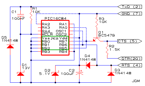
The dash lines are not connected in my prototype and it's a 16F88 pic in place.
Original site is at: http://yingtongdiddleipo.ee.wits.ac.za/help/picprog.html#3

Prototype board with pic in place:


PIC programmer in action:


Piklab version is: 0.15.0
Configuration is: JDM classic (delay 20)

Will probably make a more permanent programmer (in a PCB) but for now it's ok like this, I just needed 1 pic programed.

Now I already have the PIC in place on the APRS TNC PCB and look's that is working good, I have the command prompt and can issue commands! Unfortunately the shack computer is not working well so will test live reception in the near future, probably transmission also.

What a blast!

After some days without success in some experiments, today was a very productive day.... I just blasted what's left from my DVD reader, I say what's left because he stopped working....I checked the fuse and replaced by a piece of wire (that's plain wrong I know) although having noticed some burned pcb parts I went for it. So I wasn't expecting to much except that 1 second before I though maybe it was a good idea to put the safety googles...before powering up for testing...
Here's the outcome:


The cooper wire over the fuse simply vaporised in front of me... how fun can that be!? :)
Never mind, I just got a new box for some future projects. That's what gives to buy very cheap electronics... they just don't last!

Tuesday, November 16, 2010

13.8V 20A power supply

...Well it's more like 13.7V and probably 20A power supply since that's the transformer secondary current rating.

I have this project for finish since 2002, it was for some time built but I didn't like the original schematic and now I changed. The original schematic was based on a LM7812 but that creates problems isolating the output transistors (2n3055, what else!). Now it's a more elegant solution based on a 7912 for voltage "control".

here's the schematic:


It is advisable to put an over voltage protection (due to circuit nature and in case any of the "gnd" diodes fail) circuit but for now it's ok for me.
This is a ground regulation circuit so makes it possible to have the collector of the 2n3055 transistors to case avoiding the mica insulators. The output capacitor is critical, without it the 7912 has a tendency to oscillate. The 2n3055 base connected capacitor should be 2.2uF (if tantalum) per amp (on the 7912) or 10 times more if electrolytic, so a 22uF should be enough but the more the better...

Now the working unit under load test (FM mode, high power setting on the TS-50) to a dummy load (didn't measured the input power):


Some more crappy photos:

The ugly "control" board:

The finished "product":


For now there's no need to put any fan (that's not an optimal dissipator position) because on a normal qso the output transistors don't get enough warm).
Have fun!

Monday, November 08, 2010

VHF FM transmiter using the Si570 (21.4 IF)

Here's the schematic for the new VHF FM transmitter. it's not production grade so please don't try to build this unless you know what you are doing and have an interest in share improvements. With different output filter and amp (none at the moment) I am sure this could be made in to an 10m to 2m FM transmitter, the only limit being the Si570 output frequency capability.


I have to find a 21.4Mhz filter for future testing. Audio is nice but can always be improved. In my prototype both ampop's adjust trim pot are at mid scale.
The core in the coil connecting the NE602 input is a red one (first one if found in the box) and there's no core at the oscillator tuned circuit, just air and near coupling.
Ceramic 10.7Mhz resonator is from one of those cheap AM/FM radios. A crystal would not work nice (to low capacity in the varicaps?) and also tested with negative result with an normal ceramic filter at the earlier prototype stage.

Sunday, November 07, 2010

A lot of issues...

The "pic" on the VHF FM tx just got un-programed.... during tests I cycled the power on butom too fast and that for sure affected something in the internal memories... now it tunes from 148 to 152 and doesn't let me going down or up from this loop....ooh well! I will program the chip again. Anyhow I allready manage to make 3 QSO's with the radio.

Put myself making a simple packet TNC using a pic 16F88 but my simple pic programer refuses to program this model, from what i've searched I am not the only one with this issue... if you have programed the 16F88 with a simple programer please let me know the shcematic...

The simple packet TNC (once programed) will connect a VHF single channel data transceiver module I bought the last ham fair I attened....the programer is as simple as 2 diodes from rs232 txd and rxd to the program pin on the module (connects internaly to RB3 on the PLL PIC)..how dificult can it be?...doesn't work! Trying to sort this one out is driving me crasy! The VHF module is still programed in 156Mhz not exactly what I want...

The simple DT-102 module programer

..I also connect ping 4 on the VHF module side to ground, I think it was missing in the shcematic....see the internal module schematic an let me know if I am not right on this decision.


...pin 4 is ground...anyhow it doesn't work this way or by the programer schematic! Must try in another computer, could be something on the rs232 side....but my another computer doesn't have a floppy drive (to boot the programer software that runs in DOS)... I have a programer software version that runs on Windows...but hell, I will no put that #$%it on any of my computers! :)

On the more or less good side I built a smal VHF FM test transmiter using an 10.7 ceramic ressonator modulated by a varicap to mix the double frequency (21.4) with the Si570 VFO....now, since I don't have a 21.4 filter... I have the 2m frequency output plus or minus 21.4 and 10.7... but at least it works. The mixing is done in an NE602, as soon as I start sorting this issues I will probably use this for transmiter since the Si570 can give the channel step the PLL doesn't.
Here is the test board. The unfiltered and un-amplified test output is just a small piece of wire to pin 5 on the NE602:


I am also looking for a 12.5Khz step PLL replacement for the allready built VHF FM transmiter, this two options look promissing:

http://sq6ade.elektroda.eu/tsa6057.html

http://www.garex.co.uk/AKD/2001_12.5.htm

...Anyhow, no LCD and in both cases a TSA6057 pll chip is needed

Wednesday, November 03, 2010

Bench audio amp

Nothing special here, something I wanted to do for a long time.
When working (testing) with receivers there's no need to build an audio amplifier for each one (test), so why not make an universal one and putting all together in a nice little box...

I didn't draw one of my fantastic s schematics since you can build based on a better one, this one is easier to follow...

Mine doesn't have the capacitor between pin 8 and 1 (gain). The bypass is a 10uF capacitor and the 10 ohm is an 1 ohm resistor. Input dc blocking cap was added.

The final result:

On the right the input impedance tester and a 50 Ohm dummy load in a round tuna tin. on the left the frequency meter and the dip meter box.
And before being placed in the box: